Facebook
 Google
 GitHub
 Linkedin
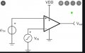
Check Post #8.I see why this is not working, try this modification:
View attachment 255659
In the original circuit with the pullup resistor added and pin 3 connected to ground the reference voltage for the + input goes to ground when the output goes LOW. At this point the capacitor cannot discharge low enough to switch the output back HIGH.
Added R3 to set the reference and R1 now provides hysteresis.
")