Problems with the Slayer Exciter Project

Thread Starter

Andre Maia 1

Joined Jan 31, 2018
3
Hello everyone reading this post! First of all, I don't understand a whole lot of electronics... In fact, I just started out... I'm a student and I stumbled upon this project called "the slayer exciter" and I'd like to make it work for the science fair at my school.
As you may have guessed it didn't work out that well and that's why I'm here, hopefully I'll get this fixed before the delivery...
This is the circuit:

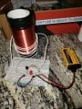
For the seconday coil, I used a PVC pipe with about 2.5 cm of diameter(1 inch) and 9 cm of height(3.54 inches) and winded the coil all the way down, for the Primary coil I wound up 4 turns in the opposite direction of my secondary coil.. I used a 2N2222A transistor and I think I connected the ports correctly ( My transistor gets really hot within a few seconds of the circuit being turned on ) I used a 22k resistor.

Slayer.png DSC_0031.JPG
My main objective is to light up a fluorescent bulb when it gets close the coil...

I have some questions regarding electronics as well.
1. Can I use common copper wire to connect my circuit? ( my cables had a bunch of little wires instead of a solid grey wire. )
2. And shouldn't this circuit be wrong as it's open?

In the attachments goes my build, it doesn't look very aesthetic but it seems correct to me?

Thanks in regards, André
 
Last edited by a moderator:

Alec_t

Joined Sep 17, 2013
14,280
Welcome to AAC!
My transistor gets really hot within a few seconds of the circuit being turned on
The circuit probably isn't oscillating, so if the transistor has good current gain and the battery is fresh there would be a high DC current through the collecor-emitter path.
Try reversing the coil connections of the 4-turn primary coil, and/or adding an extra turn or two to it.
1) Almost any wire will do, providing it can carry the current.
2) The circuit seems to rely on inherent, stray or added capacitance across the secondary for resonance.
 

lazaABT

Joined Feb 2, 2018
11
I just made one of those a couple of days ago.
Here's a reference for the transistor wiring.

Next, it's not enough that you have the primary in the opposite direction, the direction of winding doesn't matter as much as the way you connect it. Try switching the polarity of the primary. A good indication of whether it's working is if the LED is lighting up. If it doesn't light up it means it's not working. As Alec said, there is a path through the secondary through parasitic capacitance because of the high frequency of the oscillation. A large current passes through the primary and transistor and causes a small current to pass through the secondary, which turns the LED on and blocks the transistor. If you have the coil the wrong way round it won't light the LED, won't stop the transistor but will cause even more current to flow which makes the transistor hot. The transistor does get hot but shouldn't get supper hot immediately. If turning the coil around doesn't fix it, try adding more turns to the primary, but this will lessen the voltage on the secondary. I also recommend adding a capacitor(anything between 10u-1000u) in parallel to the battery. The circuit i made didn't make an arc until i added a capacitor and increased the voltage to 15v. I also used a larger transistor(BD243) with a heatsink but it still gets pretty hot. Here's a little funny video about the circuit, it answers one of your questions, good luck!
 

dodgeball1

Joined Feb 14, 2019
1
Hi All,

I need help! I can't figure this out! I've repeated my steps again and again, but can't get the bulb to light up. Attached is an image of the schematic (sans switch) and a picture of my setup.

Here are the things I used:
- PVC pipe 6" long, 1" across
- 32AWG magnetic wire for secondary coil
- 18AWG wire for primary coil
- 2N2222A capacitor
- 22K Resistor
- 9V battery
- LED

The LED lights up - ie. a circuit is good.

What am I doing wrong?!?!
Thanks for your helpIMG_6114.jpg schematic.jpg
 
Last edited by a moderator:

lazaABT

Joined Feb 2, 2018
11
Hello dodgeball, there's a couple of things you could try.
As was the case case for OP, you may have the primary coil reversed, try exchanging the primary wires(orange and white).
But if the led is lighting up it should already be working, just check that the led is oriented correctly, i can't really tell from the picture, but it should be in reverse, you can check this by taking out the transistor and seeing if the led lights up, it shouldn't. If it does reverse the leads.
A couple of other notes:
It's a good idea to have a capacitor in parallel with the power supply, especially if it's a battery, you can use an electrolytic, about 100uF will do(not strict at all, anything that you have laying around), maybe even something like a 100nF ceramic in paralel with that.
 

Bob Zhao

Joined Aug 20, 2019
4
Hello everyone. So I guess this place is sort of old now, but I've been trying to make my own Slayer exciter Tesla coil and have been running into some problems. For some reason, the current appears to be running through the base of the transistor and out of the emitter without anything being done to the 2 coils. They are both wound in the same direction. I'm using a mosfet transistor, a 40k ohm resistor, and a 9v battery. The primary coil has 4 loops, and the secondary has about 5000. Can anyone help?
 

lazaABT

Joined Feb 2, 2018
11
Hey Bob, what kind of MOSFET are you using? Do you have an LED on the gate? would also be helpful if you took a picture and drew the circuit you built.
Try running it off 12v and maybe a better supply, the battery doesn't always work(especially on breadboard). Try putting a ~100uf capacitor parallel with the battery/supply.
When I tried using a mosfet it didn't really want to work, couldn't even get it to work with an npn darlington. You can probably do it if you have a buffer/mosfet driver between the LED and gate. Also 4:5000 is quite a large ratio, you could try using a larger number of turns on the primary.
If you want to get it working quickly just make it with an npn and it'll work.
 

be80be

Joined Jul 5, 2008
2,072
It works what I found out is you got be careful the 4 turn coil has to turn the right way and may need more turns
this one took 8 it's 1400 turns
this what i used about any npn works
slayer.png
 
Last edited:

be80be

Joined Jul 5, 2008
2,072
If it's hooked up like the picture it's not going to work you don't have the led wired to the base to ground
don't look like you cleaned the ends of the enameled wire.
Have to sand off the enamel wire on the ends and the led has to be there or 2 diodes like I show.
 

Bob Zhao

Joined Aug 20, 2019
4
Oh, the LED isn't part of the circuit. Just left it on there. I sanded the enamel a good bit, as I was able to run current through it on a different circuit
 

SamR

Joined Mar 19, 2019
5,031
Couple of quick pointers. The primary wire should be wrapped neatly without crossing itself (secondary also as much as possible). Some tape helps and does not hinder the coil field. Most of the small primaries only use 1-3 wraps. Go long and take turns off 1 at a time if needed. be80be, wrap primary same direction as secondary?
 
Last edited:

Bob Zhao

Joined Aug 20, 2019
4
The LED or a diode acts as "switch" to induce oscillation. It IS a part of the circuit so hook it up as shown in schematic.
I have, along with adjusting the number of turns in my coils. Like before, nothing happens. I'm not sure if it's with the circuit or the coils. Should I try replacing the wooden rod I have the secondary wrapped around with a metal rod?
 

lazaABT

Joined Feb 2, 2018
11
Hey Bob, it looks like you also haven't connected the emitter to ground(the purple wire), it's currently connected to Vcc. Also please check that resistor with a multimeter, but it doesn't look like a 40k resistor, looks like it could be either a mOhm or MOhm resistor. You also might have burned the transistor.

Here's what you need to get it working:
The resistor should be ~47k for 18v, ~20k for 9v. If the sparks aren't big enough you can put in a smaller resistor(up to maybe 5k) but you risk burning the transistor.
You should add a capacitor or two to your power rail(~220 uF), just be careful of the voltage ratings.

A breadboard is a crappy way to make >100kHz circuits so you need to help it out some more by having the layout be as small as possible, try connecting everything with only the element leads. and using only one side of the breadboard.
You absolutely NEED the led in the circuit, but it goes in backwards, with the anode connected to ground(take a close look at the slayer exciter circuit posted above, it has 2 diodes connected backwards, 1 red led does the same thing but it's also a useful indicator). The led will light up only if the circuit starts working.

20 coils on the primary should be good, you can probably jump to 15 coils or less. Try finding the minimum number of turns where it still works.

If the led is ON, the tesla coil is working, it may not be strong enough to make sparks but it will turn on a neon or florescent bulb. You can get it stronger by reducing the number of turns or reducing the base resistance.
If the led does not light up, try switching the primary coil wires, there is only one configuration that works.

Also please more pictures and what transistor are you using.
 

Aswinth

Joined Nov 1, 2016
30
Slayer exciter circuit is really hard to get it work in the first try. You have to tweak around a lot, and at times it gets frustrating. I have been there myself when I built one, and in the end I have noted few pointers on what to check to get it working I am pasting the same below

  1. Do not use a normal transistor in place of 2N2222, unless you know to select an exact equivalent for this transistor.
  2. The resistor 22K need not be exactly the same it can be anywhere from 12K to 30K.
  3. Make sure the 9V battery that you are using is brand new, because the cheap batteries will not last more than 5 minutes with this circuit, If you have an Arduino or something which can source you +5V you can also use that.
  4. It is completely fine for your coil to have any number of turns, but it should have a minimum of at least 150 turns, you dint have to be very accurate with the count.
  5. The circuit can work from 5V to 10V. However don’t push more than 500mA through it
  6. The LED has a different purpose other than glowing, it is actually used to switch the transistor so do not ignore it, a RED colour LED will work fine.
  7. Your LED might or might not glow when the Circuit is powered, you do not have to be worried about it.
  8. You might or might not get a spark (arc) at the free end of Secondary coil, you do not have to worry about that either. If you get an Arc do not touch it.
  9. Always check if the circuit is working only by using a normal CFL bulb.
  10. Adding a metal load (foil paper) on top of secondary coil is optional, but it sure will improve the results but not mandatory to get a basic working output.
  11. There is a very little chance for you to hear any hissing sound, so don’t expect it.
If you want to know the complete build details here is the link to my Tesla coil project

Most times the problem will be with the way the coil is wound also if you have some clamp meters laying around you can use that to actually check if you coil is putting out something, these meters show slight deflection even for a small EMF output from your coil
 

shortbus

Joined Sep 30, 2009
10,045
Why, oh why, do you people keep calling these, Slayer coils, Tesla coils??? While they may make a high voltage output they are NOT Tesla coils. They are self exciting induction coils.
 

Aswinth

Joined Nov 1, 2016
30
:oops:I am sorry at the time of writing the article I dint know the difference. Completely agreed with Shortbus, these are Slayer exciter circuits and are not Tesla coils. But you can kind of get the same fun building it
 

jsan

Joined Oct 3, 2019
2
I just got started on making a few of these for a Halloween project I have the circuit breadboarded and the LED comes on but it is not lighting a CFL. I have tried all of the troubleshooting methods in the thread with no luck. I am using 18 gauge doorbell wire fire my primary and 32 magnet wire for the secondary. I'm wondering if maybe my secondary is too short. I used 1.5 inch diameter PVC at approximately 5 inches long.
 

Attachments

Top