Problems reversing a field-wound motor driven by an electronic speed controller...

Thread Starter

Dodgy Geezer

Joined Nov 30, 2009
177
I have an ongoing interest in reversing the vintage Taycol series of field-wound model boat motors using a standard radio control electronic speed controller (ESC). An ESC takes the radio control signal and outputs a PWM current to the (brushed) DC motor. We are running with a 7.2v battery.

The problem is that the ESC simply reverses polarity to reverse a (brushed) motor, while if you reverse the polarity on a field-wound motor the motor continues in the same direction. See this older thread for my earlier attempts. - https://forum.allaboutcircuits.com/threads/problems-reversing-a-field-wound-motor.76145/

You can arrange for such a motor to be reversed using diodes to force one set of coils to stay the same polarity - see here: http://taycol.tk/Rectifier.html
But this loses a few volts from the top speed. A better design would involve detecting the polarity on the input wires, and using this information to switch a relay when reverse was called for - which matches the original design requirement from the 1950s - see here http://taycol.tk/tayins501a.jpg

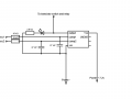
So I set up an LM358, as suggested by crutschow 6 years ago. The circuit is simple - direct connection of the LM358 comparator lines to the power input via a couple of 15k resistors to suppress current flow. But, just driving a signal diode output, I am getting some strange results.

1 - the LM358 works pretty well when forward power is applied, and it is required to output no signal. But, if I alter the speed rapidly, I get slight flickering on the signal diode. I attribute this to back EMF from the spinning motor.

2 - when reverse power is applied, I initially get a strong light from the signal diode. That would be at around half the PWM cycle - an equivalent multimeter voltage of some 3v. By the time the duty cycle reaches 90% the diode is weak and flickering a lot - and it goes out completely at 100%. Possibly this is a back EMF effect as well?

It would obviously be damaging and dangerous to put a control system in a model boat when reverse might suddenly switch to forward - or vice versa! I suspect that there is some way to address this problem - but I'm not an electronics specialist and hope that someone out there might know how it's done?
 
Last edited:

MaxHeadRoom

Joined Jul 18, 2013
28,617
Is there any way you can get access to the field coils and simply reverse them when required using a relay set up, this could be triggered by a spare channel on the TX, often CH 5 & 6 are on/off types.
Presumably the operator would take the RPM to zero first.
Max.
 

Thread Starter

Dodgy Geezer

Joined Nov 30, 2009
177
Presumably the operator would take the RPM to zero first.

Unfortunately we could not rely on that. The operator would have a single stick giving forward to reverse with neutral at an indeterminate centre, and his full attention would be on controlling the boat. One slip and the propeller or the motor shaft joint would strip off.

I have tried an approach which used the second channel (the sticks are usually 2-function) to switch the relay with a mechanical detent forcing the controller to bring the stick to neutral, swing it across and then continue down - but it is a kludge and depends on the layout of the controller face. A lot of boats use the 2-function car-type controller anyway....

What I had hoped for was a simple circuit I could wire into the power supply which would be generally applicable to anyone using a Taycol. I am sure it is possible - just not sure how.
 
Last edited:

MaxHeadRoom

Joined Jul 18, 2013
28,617
I would have though most would use a P.M. field motor these days, but I gather these are vintage motors?
The way I see it, you going to have to reverse the field, regardless.
I see from the link that these are series field motors, which offers very high torque but very poor speed control due to RPM dependent on load.
Max.
 

Thread Starter

Dodgy Geezer

Joined Nov 30, 2009
177
I would have though most would use a P.M. field motor these days, but I gather these are vintage motors?
The way I see it, you going to have to reverse the field, regardless
.


This is correct. I run that Taycol website, and the idea here is to provide a circuit which will allow people who run these motors in vintage boats a better way to integrate their old motors with modern control gear. The rectifier approach has the benefit of simplicity, but loses volts, and since it feeds stator and rotor separately, has the danger that a failure of one circuit or connector means all the power goes through the other, ruining a vintage motor. The series design neatly protects against this.

What I cannot understand is why the LM358 does not output a signal when the polarity is positive (correctly), then changes to putting out a signal when the voltage is negative (correctly), but only up to about 3/4 power (about -5v). Then, as I increase power on the negative cycle, the diode goes out, indicating that the signal stops. If it works up to -5v, why not up to -7.2?
 

Thread Starter

Dodgy Geezer

Joined Nov 30, 2009
177
Looking at the signal at the diode I see that it comprises a set of pulses, and as the power rises these get narrower - eventually stopping, which is when the diode goes out. My problem seems to be associated with teh fact that I'm driving the LM385 with a series of pulses rather than a constant voltage level. Is there a simple way of smoothing out a series of pulses into a single voltage level?
 

Thread Starter

Dodgy Geezer

Joined Nov 30, 2009
177
I have tried putting in a couple of capacitors - the circuit now looks like the enclosed diagram.

It now detects negative polarity fine, but keeps detecting as I ramp up the positive voltage to about 1.5v - which might be OK in practice, as these big motors won't turn with so little potential. But it would be nice to get it switching precisely. I looked at the ESC output with a scope and saw that when the diode was on in the positive phase, the square waves had a little bite out of them, which seems to be associated with the spurious detect. I enclose a scope photo - 5v per cm, and 0.2ms.
 

Attachments

MaxHeadRoom

Joined Jul 18, 2013
28,617
So using this set up how do you actually reverse the motor, operator procedure etc?
I am now quite seeing the whole picture?
Max.
 

Thread Starter

Dodgy Geezer

Joined Nov 30, 2009
177
So using this set up how do you actually reverse the motor, operator procedure etc?
I am now quite seeing the whole picture?
Max.
Quite straightforward. You accelerate the motor forwards, and the ESC drives it forwards with positive polarity. You move the radio control stick back to 'neutral throttle' - which will be the central position - and the motor will stop. You continue pulling backwards to go into reverse, and as the ESC switches over polarity, the circuit detects this and throws a relay. This relay switches the field coil from one polarity to the other, so now when the motor is energised it will go in reverse.

For a field wound motor the polarity of the power it is fed is irrelevant- it will always go one way. Only if you reverse the field coil (or the armature) will it go in reverse. The circuit detects the ESC calling for reverse, and reverses the field coil with a relay....
 
Last edited:

MaxHeadRoom

Joined Jul 18, 2013
28,617
For a field wound motor the polarity of the power it is fed is irrelevant- it will always go one way. Only if you reverse the field cool (or the armature) will it go in reverse. The circuit detects the ESC calling for reverse, and reverses the field cool with a relay....
Yes I realize that, just still confused as to where you are as to what you need, I assume it is the reversal detection circuit?
Max.
 

Thread Starter

Dodgy Geezer

Joined Nov 30, 2009
177
Yes. I thought it would be simple to use an op-amp comparator as I had been advised, but I do not seem to get a clean detection at the cross-over point. I am just using an led to indicate what the output signal is doing, and it seems to go high whatever polarity is being presented to the detection lines.

I think the problem may be to do with motor back emf, or perhaps the fact that the input is not DC, but PWM. Putting some smoothing caps on the line has improved matters, but it is still not ideal.

I suspect I may have to match the caps to the ESC frequency to get the discharge cycle right - and I don't know go to do that...
 
Last edited:

MaxHeadRoom

Joined Jul 18, 2013
28,617
I have been thinking the issue over, but I have been out of the RC arena for a while and only used the BLDC motors, but a few questions.
Do you know the frequency of the PWM output to the motor.?
What is the motor supply voltage?
I assume there is a bit of hysteresis when going from fwd to rev through zero, IOW what is the PWM read at the motor when the motor just start to turn, (fwd or rev)?
Max.
 

Thread Starter

Dodgy Geezer

Joined Nov 30, 2009
177
Hmmm...

The idea is to offer this circuit on the Taycol board, so it might need to cope with a number of different installations.

1 - PWM frequency. Looking at the scope picture, that's about 2.5kHz. But ESCs can be anything from 1kHz to 20kHz....
2 - Motor supply voltage. Typically, Taycols are 12v. A common model boat battery is 7.2v, which is what I'm using. They may be run on as little as 6v. There are claims that the bigger Taycols can take up to 20v, but I haven't heard of anyone doing that....

At zero all readings are zero, of course.

When the motor is powered in reverse, and the output should be ON, the LED lights up strongly and the average voltmeter voltage climbs through -0.1 up to about -1v, where the motor starts turning. That would be about 30% duty cycle, and is about where the scope picture is. It stays on strongly as the voltage climbs to -7v or so.

When powered forwards, the LED turns out promptly at zero, then flickers back on a bit as the average voltmeter voltage climbs through +0.1v to +1v, which is where the motor starts to turn. From about 1v the LED goes out. The scope picture shows the waveform down at about the 30% cycle.

You will see that the waveform is a pulse, with a capacitor decay after it. That is the area where this anomalous LED signal happens. At 50% the waveform is square, with no cap decay, and the LED behaves properly.

I suspect that the cap smoothing is just too simple, and a better way of changing the PWM to DC is needed.. Or maybe I just need to get the right cap value?

I was thinking of using a D882 to switch the relay - does that seem reasonable?
 

Thread Starter

Dodgy Geezer

Joined Nov 30, 2009
177
My preference now is a power Mosfet if possible.
Max.

All things are possible - but I'm not an electronics specialist. My background is Mediaeval Philosophy...

How would I use a Mosfet? I have some IRF540Ns at this end if that would help... Are you talking about using it for the detection process currently performed by the LM358, or the switching performed by the D882 and the relay?

To reverse the field coil I need a DPDT crossover - which a relay can do, but I don't think a Mosfet can....
 

Thread Starter

Dodgy Geezer

Joined Nov 30, 2009
177
I thought that the output from the LM358 would be max volts - in this case 7. 6v would be the minimum. Are you saying that the D882s won't switch at 6 volts?
 

Thread Starter

Dodgy Geezer

Joined Nov 30, 2009
177
I'll run with what I've got here - but will keep the Mosfets in mind. At the moment I think that if I can get the cap values right I might be able to run it as it is...
 

Thread Starter

Dodgy Geezer

Joined Nov 30, 2009
177
Well, after experimenting, I still get the LED shining when it should (when going in reverse) but also shining when it shouldn't (going at low speed forward). At full speed forward it shuts off, as expected.

I decided to take away all the capacitors and run the LM358 with no smoothing at all, to see if I could see what was going wrong. And I found an interesting item.

When going in reverse, the ESC puts out standard PWM pulses, and these go through the LM358, and turn the LED on (with pulses, but it looks solid due to vision persistence). Which is as expected.

When going forward, the pulses should be blocked by the comparator. But, at slow speed, they are not. And what comes out at the LED end is an odd signal - I enclose a picture. You will see that the pulse occurs i a positive direction, but just before this there is a sharp negative-going spike. Is this what is turning the MM358 on/? Where is it coming from? And how can I stop it?
 

Attachments

Top