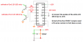
Not s dumb plan at all, but rather not understood by many of us. The difference between the 7400 series and the CD4xxx series is that the74 00 is a replacement for TTL, running at TTL voltage of 5 volts, while the CMOS CD series can work very well at 12 volts, and some of them even higher. So they are not always plug-in interchangeable.
And for whole light strips running on 12 volts, there will need to be some sort of driver interface, depending on the current the LED strips require. We don't know that so which transistor to pick is unknown.
Create 5 controllable relays for DIY LED light fixtures.
Important relay control parameters:
Relays will be triggered by 2 independent, manually selectable pulse circuits with “if achievable”, a LEF Fade Out circuit.
Piezo pulse generating circuit much like a Piezo Drum Signal Conditioning circuit. Reference circuit.
Standard Timing Pulse Generator “555” with potentiometer pulse rate control.
Potentiometer controlled LED “fade out rate” circuit paired with circuit 1 or 2. Optimal control of this circuit would be to omit potentiometer & link partnering circuit’s pulse rate to fade out rate.
A WS2812b strip requires a controller. You cannot simply give it power and have it light up, you have to transmit 24 bits of data for each LED on the strip with specific timing. A microcontroller or other programmable device is the only practical way to do that.
A WS2812b strip requires a controller. You cannot simply give it power and have it light up, you have to transmit 24 bits of data for each LED on the strip with specific timing. A microcontroller or other programmable device is the only practical way to do that.
A WS2812b strip requires a controller. You cannot simply give it power and have it light up, you have to transmit 24 bits of data for each LED on the strip with specific timing. A microcontroller or other programmable device is the only practical way to do that.
OK, there is some serious confusion between what I see in the picture and what BOB is describing. Not just a bit different but a HUGE DIFFERENCE.
The strips in the picture in post #85 are rather different from what BOB is describing.
The good news is that thencontrol scheme for a strip as shown does not require any digital processor to generate a bitstream to control individual LEDs. The light intensity can be controlled over a wide range by adjusting the current, which is controlled by changing the supplied voltage. So we are back to what has already been discussed, and we still do not know the exact current. But we do know the power supply voltage and we have a reasonable grip on the switching scheme. And a fair clue that the description does not match the reality, which in this instance is good.
So it turns out that the packaging label said WS2812B which i took for fact.
I ordered the lights a over a year ago when i began this project. But shortly after my eldest son was having difficulties in school on many levels. He was assessed by a neuropsychologist and was codes for ADHD and Autism which lead to a very difficult year of many adjustments. I paused everything for him.
Now i’m able to get back to this, but some details i had were fuzzy.
i went through my emails and found the original invoice and the lights are as follows:
SMD 3014 LED Strip 5m - 8mm Width 120LED/meter DC12V
Electrical :6w/9w/12w/17w/m , DC12V
This is what i was able to locate on the particular LED
A MOSFET can be used as a switch to supply 12V to the strips when the 5V signal from your pulse circuit is high. This is not an amplifier, it only has two states, off and on. An amplifier would take any voltage between 0 and 5 and turn it into a corresponding voltage between 0 and 12. You do not need an amplifier.
A MOSFET can be used as a switch to supply 12V to the strips when the 5V signal from your pulse circuit is high. This is not an amplifier, it only has two states, off and on. An amplifier would take any voltage between 0 and 5 and turn it into a corresponding voltage between 0 and 12. You do not meed an amplifier.
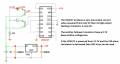
Okay, so the 555 timer & CD4017 works fine with 12 volt and eliminates my voltage drop to the LED strips.
But the piezo is locked to 5v as per referenced and test circuit designed for a piezo drum circuit. using a different component as you’re suggestion would be placed where at the end of my piezo circuit and bump it up to the necessary 12v spike to pulse the clk in the CD4017?
The LED strips have 120 LEDs per meter in series strings of 3 (30mA per 12V string) and the strips are 5 meters long. Then the current for each 5 meters is 6A. IRLZ44N Mosfets can drive each 5 meters fine with a 5V signal input.
The CD4017 IC will turn on only one 5 meters LED strip at a time.
That 35 mA Max was for a single LED. If you power a whole 1 meter strip with 120 LEDs arranged as 40 of the 3 LED strings plus a resistor you will still need a driver circuit able to handle that current, which might be almost 3 amps.
I did not see any circuit that limited the sensor voltage to5 volts, so it may have been in a link I did not follow, if it was a youtube link.
Where does a 555 timer get into the discussion??? What it it doing for the application?? If a timer is required us a CMOS IC timer that can handle 12 volts easily. MC4538, MC14538, or others.
The LED strips have 120 LEDs per meter in series strings of 3 (30mA per 12V string) and the strips are 5 meters long. Then the current for each 5 meters is 6A. IRLZ44N Mosfets can drive each 5 meters fine with a 5V signal input.
The CD4017 IC will turn on only one 5 meters LED strip at a time.

 Facebook
 Google
 GitHub
 Linkedin

 99.9 KB Views: 6