OK, now it is confusing in that it is not clear if the count is to advance with each separate bass drum hit, or with each cycle of bass drum vibration. THAT could be an awesome effect. And to operate with the very minimum of components, use MPSA13 darlington transistors to control the LEDs, they can be driven directly from the 4017. I have used exactly that in a commercial product that has been good enough for an auto maker to use on the production line for many years. So it works very well and is very reliable.
OK, now it is confusing in that it is not clear if the count is to advance with each separate bass drum hit, or with each cycle of bass drum vibration. THAT could be an awesome effect. And to operate with the very minimum of components, use MPSA13 darlington transistors to control the LEDs, they can be driven directly from the 4017. I have used exactly that in a commercial product that has been good enough for an auto maker to use on the production line for many years. So it works very well and is very reliable.
So the grand plan is to have a piezo on both the bass drum skin and the snare skin. When the kick drum mallet hits the skin, or drum stick hits the snare it triggers a voltage in the piezo which would be used as the clk pulse to step up to the next 4017 pin.
Each “Q” pin being connected to the base of the transistor which allows the 12v to power the led strip connected to the emitter of that pin’s transistor.
Issue that i’m having is that the voltage passes multiple pulses with on strike of the drum. I believe due to the AC producing multiple + spikes in one charge when sensing the drum strike.
It's easy enough to suppress the signal from the piezo to one pulse but it requires a delay before the next pulse arrives. So the new problem is the 4017 will miss some of the hits from the drums because of the duration of those multiple spikes and how fast the drums are hit.
The solution is setting the time on the pulse stretcher so that it is always less than the time between drum hits but longer than the piezo voltage pulse. So the pickup does not go on the resonant head, but on the beating head. That means not on the second skin where the snares work.
An interesting option would be to use a comparator to catch the single highest peak But it would not sense softer peaks.
Have you considered microphones instead of piezo sensors?
Thank you, i am aware and will at the least have a disclaimer. But i am hoping to find was of refining control over rate of response. But for now i just need to get the circuit functional. As a novice i’m a little discouraged with my lack of comprehension and ability to immediately pivot using the recommendations.
Just to assure i understand as i’ve previous mentioned, i’m still very much in the beginner phase of this journey. This circuit would just be for creating and adjustable pulse/trigger?
because i will give it a world, i just eant to make sure before i order components haha.
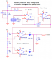
The circuit shown provides adjustable gain but no means of adjusting the offsets or limits. So while it is undoubtedly perfect for some applications it does not contain any scheme to directly prevent excess pulses from an input with multiple peaks.
And the device, a MCP6024, does not have the actual power connection scheme shown. Can it operate on 12 volts? Tha is unknown to me.
So a bit of additional explanation is required.
Just to assure i understand as i’ve previous mentioned, i’m still very much in the beginner phase of this journey. This circuit would just be for creating and adjustable pulse/trigger?
because i will give it a world, i just eant to make sure before i order components haha.
Yes, it just generates pulses, but it's very sensitive and adjustable, it produces a pulse from positive or negative going input.
I designed this to fix the timing and sensitivity problems I experienced due to sensor phasing, this circuit doesn't care.
The output of the piezo looks like a highly damped sign wave, the leading edge can be positive or negative, if you only trigger on one of the edges, it might be delayed relative to the others in the system, depending on the phasing.
Yes, it just generates pulses, but it's very sensitive and adjustable, it produces a pulse from positive or negative going input.
I designed this to fix the timing and sensitivity problems I experienced due to sensor phasing, this circuit doesn't care.
The output of the piezo looks like a highly damped sign wave, the leading edge can be positive or negative, if you only trigger on one of the edges, it might be delayed relative to the others in the system, depending on the phasing.
The MCP6024 is a 5 volt part. Yes, you might register more than one pulse, but with sensitivity adjustment, you can get one clean pulse (most of the time) as the leading pulse is always much bigger than the rest.
The piezo device on a drum head probably has a greater amplitude than whatever the device application that the circuit shown was for. That is why I suggested the timer, because it will mask the additional peaks that follow immediately. So the short time pulse stretcher will be required with the comparator circuit anyway. If the initial arrangement triggers then no more sensitivity is required, because the problem is multiple triggering.
The piezo device on a drum head probably has a greater amplitude than whatever the device application that the circuit shown was for. That is why I suggested the timer, because it will mask the additional peaks that follow immediately. So the short time pulse stretcher will be required with the comparator circuit anyway.
The circuit as shown works with a wide range of signal amplitudes, I found that the variation of signal level was one of the biggest problems I encountered.
The circuit could be modified to include a pulse-stretch function without too much trouble?
My original application was detecting the impact of metal balls on a MDF target board - triggering a strobe light.
The circuit as shown works with a wide range of signal amplitudes, I found that the variation of signal level was one of the biggest problems I encountered.
The circuit could be modified to include a pulse-stretch function without too much trouble?
My original application was detecting the impact of metal balls on a MDF target board - triggering a strobe light.
The circuit will generate repeated pulses in rapid sequence for a signal that has peaks with valleys between them. And on a drum head that is usually the case, Thus there must be a time delay before additional pulses can be generated. Depending o amplitude is not enough, that is already demonstrated with the multiple triggering from the direct connection. The required delay will only be a very few milliseconds.
Triggering a strobe-flash already has that delay built in, and so the problem did not exist in the original application. But the 4017 can count at several megahertz, much faster than the strobe light can flash.
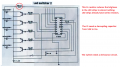
I cropped the schematic parts closer together then enlarged the schematic in post #30.
Beware of a very high voltage from a piezo that has a strong vibration. That voltage must be limited.

 Facebook
 Google
 GitHub
 Linkedin

 397.5 KB Views: 9