Facebook
 Google
 GitHub
 Linkedin
Help!!!
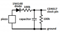
I need to know how to control the voltage spike from a piezoelectric sensor when pressure is applied.
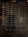
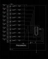
Essentially i’m using it to trigger a clk input of a decade counter. But because of the nature of the AC circuit and the pressure length. The voltage bounces making the clk jump forward pins
I need to know how to control the voltage spike from a piezoelectric sensor when pressure is applied.
Essentially i’m using it to trigger a clk input of a decade counter. But because of the nature of the AC circuit and the pressure length. The voltage bounces making the clk jump forward pins