Piezoelectric signal to pulse

Thread Starter

spokenwurds

Joined Aug 6, 2023
43
That 35 mA Max was for a single LED. If you power a whole 1 meter strip with 120 LEDs arranged as 40 of the 3 LED strings plus a resistor you will still need a driver circuit able to handle that current, which might be almost 3 amps.
I did not see any circuit that limited the sensor voltage to5 volts, so it may have been in a link I did not follow, if it was a youtube link.

Where does a 555 timer get into the discussion??? What it it doing for the application?? If a timer is required us a CMOS IC timer that can handle 12 volts easily. MC4538, MC14538, or others.
The testing, math and recommended circuit was referenced from this short video. Piezo trigger circuit reference

The timer circuit was to have a secondary lighting effect that could he switched over to with a manual pulse rate adjustment. Preferably with the option for fade out between pulses.

giving the audience a break from fast-switching during the concert.
 

Audioguru again

Joined Oct 21, 2019
6,826
Will you use 5 meters for each LED strip that will have 600 LEDs that draw 6A? That will be extremely bright.
I have only 72 LEDs like that on my computer room ceiling and they make the room bright.
 

Audioguru again

Joined Oct 21, 2019
6,826
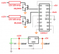
The CD4017 powered by 5V can drive each logic-level Mosfet to turn on 1 meter of Mosfets (120) with 1.2A current.
The LED strips already have one current-limiting resistor for each 3 LEDs in series.
 

MisterBill2

Joined Jan 23, 2018
27,900
OK, I finally looked at the start of that video, and what I see is hitting piezo elements taken out of piezo sounder devices. That sort of works, and is really cheap BUT it is an amateurish cobble-job at best. For sensing an actual drum played by an actual DRUMMER, I doubt that it would last in a typical Playing for Profit band setup, nor the travel to and from gigs. An actual microphone, probably a crystal or dynamic type, placed to hear each drum "participating" in the light show, will do better. Then a standard microphone connection to a simple amplifier stage that can easily be set to limit the maximum signal to what is needed for triggering a counter.
While microphones do cost a bit more than piezo sounders, they come in a package ready to use. And amplifier gain is cheap, especially if totally distortion free gain is not required. And an op-amp powered by 12 volts will not deliver a signal over 12volts. And that can certainly trigger a multivibrator (one-shot) operating on 12 volts, quite well. And the 12 volt, slightly stretched, logic signal will trigger an LED driver powered by 12 volts very well.
Crystal microphones can be cheap from cheap suppliers, as can dynamic microphones. But the crystal mics seem to be more able to survive rough handling, is my experience. Cheap quad opamps are also widely available, Possibly even electret microphones can be located at a cheap price.

So there is a system powered by 12 volts that should be reasonable to create. I do not have a favorite LED driver circuit, but there are a lot of them published. So there are the elements for the project
 

Thread Starter

spokenwurds

Joined Aug 6, 2023
43
You appear frustrated or just overwhelmed or maybe both?
Very overwhelmed.

The more i think i understand and am on track, the more i find out how little i know and how far off i am to getting a working prototype for mid September.

The rest if my band mates have been looking forward a functional set up. And i don’t think i can deliver in time.

Life happens.
 

sghioto

Joined Dec 31, 2017
8,729
It also appears there is some confusion on the supply voltages. Obviously you need a 12 volt supply for the LED strips but it's also perfectly OK to power the LM324 and the CD4017 from the 5 volt regulator as you show in post#62.
 
Top