Piezoelectric signal to pulse

Thread Starter

spokenwurds

Joined Aug 6, 2023
43
I took a break from the project today as my brain needed it with all of life’s other demands.

But i wanted to thank everyone again for all of the help. I’m learning so much. My late sister would be so stoked to see me working this project out and keeping my promised to get back into music.
 

MisterBill2

Joined Jan 23, 2018
27,899
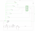
I suggest operating the circuit in post #62 on 12 volts instead of 5volts because the current available from the 4017 will be greater. I also suggest considering the base current requirements of the transistors in the full- ON conduction mode relative to the drive capability of the 4017. And why only 5 LEDs instead of ten???
 

Thread Starter

spokenwurds

Joined Aug 6, 2023
43
I suggest operating the circuit in post #62 on 12 volts instead of 5volts because the current available from the 4017 will be greater. I also suggest considering the base current requirements of the transistors in the full- ON conduction mode relative to the drive capability of the 4017. And why only 5 LEDs instead of ten???
The 5 volt control for the circuit is because of the math involved in controlling the AC spike high and width that is optimal for drum strikes.

i’m sitting at five channels instead of 10 as i’m using 5 light fixtures in our stage configuration. So using all ten channels is sort of redundant at the moment..


references pulled from this video, also helped me understand a lot more about how the components work in relation to each-other. Great for someone like myself who has a very limited understanding, but is motivated. Lol

Drum trigger circuit
 
Last edited:

Thread Starter

spokenwurds

Joined Aug 6, 2023
43
Updates:
Piezo trigger will be breadboarded as soon as i have the missing components.

Second adjustable timer trigger completed.

Last road block is finding a way implement a fade in and out option on either circuit. With rate adjustability.
 

Attachments

sghioto

Joined Dec 31, 2017
8,729
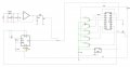
I see the Vss pin of the 4017 connected to ground through a 1meg resistor. How is that going to work?
 
Last edited:

Audioguru again

Joined Oct 21, 2019
6,826
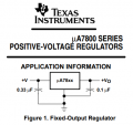
The 7805 is missing the important input and output capacitors shown on its datasheet.
If you replace the old CD4017 with a newer and higher current 74HC4017 then you do not need the transistors.
 

Thread Starter

spokenwurds

Joined Aug 6, 2023
43
The 7805 is missing the important input and output capacitors shown on its datasheet.
If you replace the old CD4017 with a newer and higher current 74HC4017 then you do not need the transistors.
Weird the simulator didn’t flag it.
I will repeat, i’m extremely knew to the world of circuit design.
 

sghioto

Joined Dec 31, 2017
8,729
It was what was originally placed when working out the Piezo, however it does work. But i i’m thinking it doesn’t need to be that large now
The Vss pin connects directly to ground.
Your schematic in post #66 has an error.
The 1M resistor should connect to the CP0 pin and ground.
 

Thread Starter

spokenwurds

Joined Aug 6, 2023
43
The 7805 is missing the important input and output capacitors shown on its datasheet.
If you replace the old CD4017 with a newer and higher current 74HC4017 then you do not need the transistors.
Okay so i compared the data sheets for both CD4017 & 74HC4017. i feel like i’m misunderstanding something. the CD supply is max 18V and the 74HC is 6V.

if i need 12V to power the LED displays i’m using how would using the 74HC allow me to omit the transistors and while still using only one power supply?
'
 

sghioto

Joined Dec 31, 2017
8,729
if i need 12V to power the LED displays i’m using how would using the 74HC allow me to omit the transistors and while still using only one power supply?
Connect the anode of each LED directly to the outputs of the 74HC4017. Connect all cathodes together through a resistor to ground as before if all LEDs are the same. Resistor value depends on LED type and current required.
Your circuit with CD4017 is only supplying 4.3 volts max to the LEDs because the transistors are configured as emitter followers.
 

Audioguru again

Joined Oct 21, 2019
6,826
Your schematic in post #66 shows single 2V red LEDs, not LED displays. With a 5V supply, the CD4017 would produce a max output of only 3.5mA into each LED (very dim) without current-limiting resistors, therefore you need transistors to increase the current and brightness.

With a 5V supply, a 74HC4017 produces 38mA which will burn out the very bright single LEDs, so current-limiting resistors are needed. Transistors are not needed.

Your schematic shows that the 12V is used only to heat the transistors, not to power LED displays.
The emitter output voltage of each transistor is only about 3.3V then the current in the 220 ohm current-limiting resistor is only about 6mA.
 

Thread Starter

spokenwurds

Joined Aug 6, 2023
43
Your schematic in post #66 shows single 2V red LEDs, not LED displays. With a 5V supply, the CD4017 would produce a max output of only 3.5mA into each LED (very dim) without current-limiting resistors, therefore you need transistors to increase the current and brightness.

With a 5V supply, a 74HC4017 produces 38mA which will burn out the very bright single LEDs, so current-limiting resistors are needed. Transistors are not needed.

Your schematic shows that the 12V is used only to heat the transistors, not to power LED displays.
The emitter output voltage of each transistor is only about 3.3V then the current in the 220 ohm current-limiting resistor is only about 6mA.
Thank you that was a fantastic explanation. I’ll give it a try for sure.

the LED fixtures are LED Strips that require 12V.

i’ve attached a tester version of the future fixtures.
 

Attachments

Top