Just some general questions about remaking something from the past

Status
Not open for further replies.

Thread Starter

Berzerker

Joined Jul 29, 2018
623
AG said:
The schematic in the patent is correct, why don't you use it?
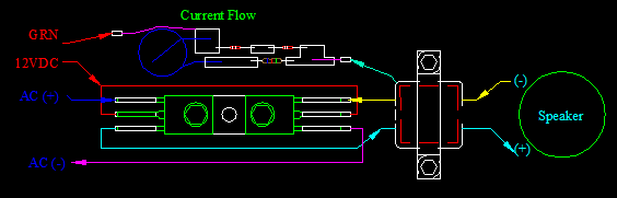
I left the ground out on purpose. That schematic is not the one I have and it's not wired that way. you would have to use a dual coil speaker which are only $45.00 but don't want to do that. I've been checking around for center tapped speakers cos the originals only had three connections. one on either side of the "-0 VAC" Radio speaker (-) or how ever you want to say it, to do the push-pull. It's missing the output transformer. The ground section that mine has, that one don't. It can use any two wire speaker. I know there are two different voltages on it (we discuss that). if you follow the wires and PCB connections through circuitry my schematic is right " if you hook the 12VDC to the bases which is what I asked".
I've also read:
poster said:
I owned a pair of Tenna Mind Blowers. I dissected one of my Tenna Mind Blower amplifiers to find out why I was measuring 25 Volts RMS across the speaker terminals with a Fluke 8060A True RMS DMM from a 12 Volt DC source. That calculated out to about 78 Watts RMS at 8 ohms with them cranked way up. They had a standard 8 ohm single voice coil speaker. The speaker leads were connected at points 45c and 46c in the posted schematic drawing. The center tapped winding that you see in the output section of the drawing is the output transformer and not the speaker VC as some have concluded here. They do not show the speaker being connected to it in the schematic.
I'm trying to copy the one "I" have.
Edit: And I did read the patent where it said 45C and 46C were the voice coil. I wanted you to read where it hooked up to a two wire speaker.
 
Last edited:

Audioguru

Joined Dec 20, 2007
11,248
25V RMS at 8 ohms "cranked right up" might be the 12.5V RMS measurement of the original low distortion signal plus another 12.5V RMS for all the severe distortion harmonics. (12.5V squared)/8 ohms= 19.5 real Watts.

In the patent and on their schematic it says and shows that 45C and 46C are the amplifier emitters. The ends of the voice coil are said and shown to be CL1 and CL2. The center-tap of the speaker is CL3.

The patent does not mention a two wire speaker but it is obvious that it would need a powerful center-tapped output transformer on the amplifier to drive it.
 

Thread Starter

Berzerker

Joined Jul 29, 2018
623
AG said:
In the patent and on their schematic it says and shows that 45C and 46C are the amplifier emitters. The ends of the voice coil are said and shown to be CL1 and CL2. The center-tap of the speaker is CL3.
Didn't have the schematic actually pulled up on my computer I just went by his numbers.
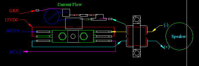
OK I can just hear "wrong" in your next post but here it goes. I left out the input transformer on purpose. I pulled out my magnifying glass now and made sure. and regardless of pin layout on the transistors the arrows show the flow, where the wires go to, even if it's on the PCB or a component attached to it. This time I'm gonna use my "sketch" I think it will make better sense. remember no pin layout just flow.
 
Last edited:

Audioguru

Joined Dec 20, 2007
11,248
The resistor that feeds current to the two diodes is not shown connected to +12V on your sketch.
Your sketch is useless without the proper transistor pins.

The direction of current flow does not matter. You simply need to know how transistors work and how circuits work.
 

Thread Starter

Berzerker

Joined Jul 29, 2018
623
AG said:
The resistor that feeds current to the two diodes is not shown connected to +12V on your sketch.
That's because there is only one resistor on the whole board and it is nowhere around the +12V. It is on the PCB as shown.
Everything is in the place is as shown. Your still going by the schematic you showed me and not by what I have. There is nothing missing "But" the input transformer. And flow does matter cos if it didn't I could just hook anything to any other thing I wanted and it would just work.
You keep posting that I hook the so and so to the wrong thing and it won't work? well that has to do with how the current passes through the resistors don't it?
Edit: I thought that was what the arrows represented on a transistor diagram was flow.
Edit 2: If going by the MJE270 the left transistor top=B, middle=C and bottom=E
 
Last edited:

Audioguru

Joined Dec 20, 2007
11,248
The bases of the transistors are the signal inputs, not the outputs. The emitters are the outputs. The patent says it and shows it on the schematic.
Are the metal bases of the transistors on the bottom where you cannot see them? If the metal bases are on top then of course the pins are reversed.

The arrows on transistors show if they are NPN or PNP. You need to learn the correct polarities and how transistors are used, not the direction of holes or electrons flow.
 

Thread Starter

Berzerker

Joined Jul 29, 2018
623
Now that made sense AG. and I have been trying to teach myself. Wish you would have just posted that in the first place. and my sketch shows +AC signal input on the transistor Base (B) using the MJE270 and the others I have been looking at to replace them. I also have been trying to find a "good" explanation in the difference of a NPN and a Darlington NPN. I do read everyday and I am trying, it's just that it's new to me and I have to fill some gaps in my understanding of it all.
Again Thanks
Edit: after reading it very carefully again I want to know if your talking about the bottom where the transistor is bolted down to the aluminum plate? I thought that was to draw off heat. I noticed when I took the one apart it still had some thermal paste on it.
 
Last edited:

Audioguru

Joined Dec 20, 2007
11,248
The power transistor in that old package has a metal base on its bottom side that feeds away its heat to a metal heatsink.
The part number is marked mon its top side where it can be seen.
The pins are usually shown from a top view.

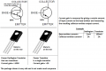
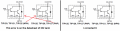
Here is my explanation of a Darlington power transistor and an ordinary single power transistor:
 

Attachments

Thread Starter

Berzerker

Joined Jul 29, 2018
623
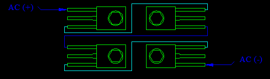
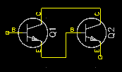
On to my next stupid question..... If two can amplify (X) amount and you get (X) watts out of them then couldn't you use 4, 6, or even 8 to get more watts? example:

I've been looking around to see if they have chip that does this all in one (the Darlington pair). I've also been thinking about hooking the one I still have intact to 12DC and see what happens. But it scares me that they are so old that I've been holding back. And if you are talking about the bottom of the transistor that bolts down wouldn't that be like grounding it? And if I'm starting to get it then the VAC and VDC kinda piggy back each other through the transistor like sound does with video on your TV right?
 
Last edited:

Audioguru

Joined Dec 20, 2007
11,248
Power= (voltage squared)/resistance, or (current squared) x resistance.

If the speaker is 4 ohms (common for a car speaker) and the DC power supply voltage is 14.4V in a car then the maximum undistorted output power is the RMS signal voltage squared then divided by the 4 ohms of the speaker.

The amplifier is not perfect since it has some voltage losses, maybe 2.5V. Then the maximum output peak-to-peak AC voltage swing is 14.4V- 2.5V= 11.9V.
The conversion of peak-to-peak to RMS is dividing by 2 x pi (pi= 1.414), so the 11.9V/2.828= 4.2V RMS.
Then the max undistorted power in the 4 ohm speaker is (4.2V squared)/4 ohms= 4.4W.

Double the power supply voltage or use a bridged pair of amplifiers then the power output into the 4 ohm speaker is almost quadrupled to about 15W. Quadrupling is because the voltage swing is doubled and the resulting current is also doubled.
Doubling the number of transistors does not increase the output power but might be needed to share the heat.

Use a 2 ohm speaker instead of 4 ohms then the power from a single amplifier is almost doubled to about 8W and the power with a doubled power supply voltage or a bridged pair of amplifiers is almost doubled to about 28W.

AC is a voltage and current that alternate going positive and going negative. A car does not have two batteries, it has the positive battery but not a negative battery, so How can the amplifier produce AC that goes positive and negative? Simply bias the output voltage of the amplifier at half the positive supply voltage then the output can swing up and down making the AC signal, or use an old center-tapped transformer.
 

Thread Starter

Berzerker

Joined Jul 29, 2018
623
Here's where your math messes me up
AG said:
The conversion of peak-to-peak to RMS is dividing by 2 x pi (pi= 1.414), so the 11.9V/2.828= 4.2V RMS.
Then the max undistorted power in the 4 ohm speaker is (4.2V squared)/4 ohms= 4.4W.
pi =3.141 so 2 x pi = 6.282
and when you divide it, pi / 2 =1.570
 
Last edited:

Audioguru

Joined Dec 20, 2007
11,248
I have been calculating with 1.414 and 2.828 for so many years that I forgot where they came from.
Maybe I should say peak or maximum power and not say its horrible amount of distortion like in amplifier ads.
 

Thread Starter

Berzerker

Joined Jul 29, 2018
623
Been looking at you transistor pics and the difference in a Darlington and a NPN.
So does this mean that this symbol:
is just two of these but already shown together like this:

.
 

Thread Starter

Berzerker

Joined Jul 29, 2018
623
Maybe I could have asked that better by asking: It's just a symbol that shows it's a Darlington transistor not that there are (two) separate transistors already put together and hooked up. In other words I would still need to use two transistors in my schematic and use the Darlington symbol to show it's a Darlington and not a normal NPN or PNP.
 

Audioguru

Joined Dec 20, 2007
11,248
I don't know if old darlingtons had two separate transistors joined together.
Modern darlingtons are made as an IC with the two transistors, a diode and two resistors (to help turn them off quickly) integrated on one chip:
 

Attachments

Status
Not open for further replies.
Top