LM723 Linear Regulation opamp schematic questions

Thread Starter

greenisland

Joined Jan 7, 2020
93
Hello, could someone please throw some light on this for me.
I have been reading and experimenting with linear regulation using opamps as comparators with some success, and using an opamp to control current prior to voltage regulation.
I have noticed with two old ham 13.80v linear power supplies I have, each transformer has two windings, one small around 6v ac and a larger around 17v ac, the 6v is used to power a control board with a LM723, this then controls the large pass transistor on the 17v rail.

My question is this: If the 6v ac is rectified to around 9v dc, powering the control board with the LM723 regulator, and the regulator outputs to a small npn then a large power transistor (2n3055), both of these transistors have now lost 1.20v at their junctions lowering the max output to 7.80v at the base, how do they achieve 13.80v output?.

I know I am missing something important here.
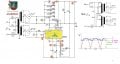
I attach a screenshot of a Spanish chap (
) on YT who explains in great detail what I'm trying to achieve with his schematic, although his schematic is strange to me , (VIDEO IS DUBBED IN ENGLISH ON ACTUAL YT)
1. his output at S is connected to pin 7 (neg) of the LM723 supply rail, short?.
2. What is the 5v zener doing at the LM723 output?, I have to put a 1k resistor here to keep the opamp draw low.
3. My main question, his LM723 is operating at 12v with the zener across its inputs, how is he getting anything above this at the final output?
Any help much appreciated.
 

Attachments

Last edited:

Danko

Joined Nov 22, 2017
2,135
About 1.5 V between base of lowest transistor and emitters of parallel connected transistors, going from LM723, is enough to close transistors and have full voltage on PS out.
 

Thread Starter

greenisland

Joined Jan 7, 2020
93
About 1.5 V between base of lowest transistor and emitters of parallel connected transistors, going from LM723, is enough to close transistors and have full voltage on PS out.
Thanks for replying
But if I get say 12v out at power transistor 2n3055, I measure 13.20v at the base of the small transistor powering the 2n3055, so the LM723 is outputting 13.20v to achieve 12.00v at positive terminal.
How is the LM723 outputting 13.20v (Spanish schematic) when it is only being supplied with 12v.
I can achieve this 13.20v using a different schematic, but using one voltage 19v dc powering the opamp and the 2n3055 pass transistor, not two low and high voltage rails.
 
Last edited:

Danko

Joined Nov 22, 2017
2,135
Question for Google:
How to turn on NPN transistor?
Answer:
"To turn on an NPN transistor, apply a small positive voltage (typically > 0.7 V)
to the Base relative to the Emitter.
This creates a small base current that allows a much larger collector-emitter
current to flow (saturation), acting as a closed switch."
 

Thread Starter

greenisland

Joined Jan 7, 2020
93
Question for Google:
How to turn on NPN transistor?
Answer:
"To turn on an NPN transistor, apply a small positive voltage (typically > 0.7 V)
to the Base relative to the Emitter.
This creates a small base current that allows a much larger collector-emitter
current to flow (saturation), acting as a closed switch."
So sorry, indeed I should keep all my questions for uncle Google and not bother the Electronic Gurus, as you wish M'lord.
Now I remember why I dislike asking any questions on this platform!, it's all coming back.
Original point about linking output of 2n3055 to ground on LM723 was contained in my original question, referring to Spanish schematic but was completely ignored (Q1).
 
Last edited:

ericgibbs

Joined Jan 29, 2010
21,390
hi green,
Hope I can help out

With the 723 -V connected to the 'S' rail output of the 2N3055's, any voltage set by the 723 appears in series with that 2N3055.
For example say the 2N3055 Vout is +12V and the 723 is set for say for 6V, pin 10 of the 723 would be a 18V , so a 5V Zener, would drop that 18V down to say 13V for the Base drive of the 2N3055.

These figures are approx but they explain the principle.
E
 

Thread Starter

greenisland

Joined Jan 7, 2020
93
hi green,
Hope I can help out

With the 723 -V connected to the 'S' rail output of the 2N3055's, any voltage set by the 723 appears in series with that 2N3055.
For example say the 2N3055 Vout is +12V and the 723 is set for say for 6V, pin 10 of the 723 would be a 18V , so a 5V Zener, would drop that 18V down to say 13V for the Base drive of the 2N3055.

These figures are approx but they explain the principle.
E
Thanks Eric, I did notice on breadboard tests that the zener at the 723 output will lower the voltage by zener v value as you have stated.
I did'nt realise the fact that the LM723 floating supply negative can be linked to the positive 2n3055 output to add to it, assuming like battery positive to negative voltage adding up.
1....So I'm safe in stating that the voltage of the floating low value LM723 control circuit value is just added to the higher voltage out of 2n3055 pass transistor.
2.... In floating the two negatives on each rail are always kept separate, yes?
 

ericgibbs

Joined Jan 29, 2010
21,390
hi g,

is just added to the higher voltage out of 2n3055 pass transistor.
Yes, equivalent to two separate batteries, in series

In floating the two negatives on each rail are always kept separate, yes?
The way the two transformers and rectifiers are configured they could be considered equivalent to two separate batteries.

E
 

crutschow

Joined Mar 14, 2008
38,316
The LM723 is rated for 40V, so I'm puzzled as to why there is a lower voltage supply to power it when controlling a DC supply of <25Vdc (?).
It seems unnecessary.

For example, below is the LTspice sim of a 5A, 723 circuit with output that goes from 2V to within about 1V of the input voltage:

1774112038119.png
 
Last edited:

schmitt trigger

Joined Jul 12, 2010
2,027
Since I understand Spanish, I decided to listen to the original video’s audio.
According to the video’s creator, the reason to have the lowest possible output ripple, the 723 shoube powered independently from the main supply.
He mentioned another video of his, where he explained that technique.

EDIT; this also allows the output to be adjusted all the way to zero.
 
Last edited:

schmitt trigger

Joined Jul 12, 2010
2,027
Got it.
Modified 723 circuit below for that:
It uses the Ref voltage to buck the 2V Inv feedback voltage at the adjustment pot output to allow the output to go to zero when the pot wiper is the top (0%) position.

View attachment 364993
Very interesting concept!

To me, all these circuits show the reason for the 723’s popularity: it is so flexible and versatile!
One can actually build a switchmode supply with it, which I did, copied from an old Unitrode app note.
 

Thread Starter

greenisland

Joined Jan 7, 2020
93
hi green,
Are there any outstanding points, on your original circuit, you want to cover.

E
Thank you Eric for all the advice, and everybody for that matter, before reaching out here for guidance I have exhausted all internet avenues, and gone down many rabbit holes into electronics wonderland and a lot of times ending up more confused. Sometimes the blatant obvious is a brick wall to a novice.
A few questions I'm struggling with on the Spanish schematic.

1...The 5.1v zener diode at pin 10, what is it's function? (previous opamp power supplies I've made, require a resistor here to keep the current output of opamp within tolerance)

2...Resistor 306 1k, I see this a lot in Darlington pairs, is it not just increasing LM723 output load.

3...Don't laugh, just clarifying..., the output is positive S, and negative centre (marked with circle and line) yes?.

4...CRUCIAL I'm thinking?...pin 6 ref to ground with the voltage control pot., is not to the actual opamp ground as normal, but referenced to the high voltage ground in the centre.

Something I just noticed, I was testing on a breadboard yesterday with an opamp TL071, with same high and low mixed supplies, but connected the inverting pin pot to the opamp ground not ground from the higher voltage, as in Q4. To the batmobile Robin, sorry I mean breadboard.

5...Last one, Am I correct in saying, there are two output conditions for a LM723, a high and a low, 1.5v to 7v and 7v to 30v.
For the lower v. range adjusting the Vref to ground is preferred, and the higher v range, adjusting inverting pin 4 to ground.

Hope I'm not testing your patience too much, your help is much appreciated.
 
Last edited:
Top