 Facebook
 Google
 GitHub
 Linkedin
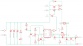
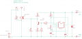
Hello! I made the power supply from the attached schematic.
I tested it using the oscilloscope, using a PSU shorter, which is a circuit with LM555 that is generating pulses through a mosfet gate and is connecting and disconnecting a load. ln case of short circuit testing the load is 0 ohms, while testing with load, the load is 7.8 ohms. The set output voltage of the PSU is 25V. The rectifier is not present into schematic, but it is connected between the 30V ac transformer and filter capacitors.
The results are:
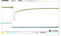
1. DS0018 = with 0 ohms at PSU shorter, and the yellow trace, CH1, on the output of the PSU, CH2, is the output of the PSU Shorter pulse generator.
2. DS0019 = with 0 ohms at PSU shorter, but with the probe on the R_Shunt resistor (on the 2 0.33R resistors).
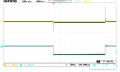
3. DS0020, 21 = with 7.8 ohms at PSU shorter, and the scope probe on the output of the PSU (yellow trace) and the CH2 probe (blue trace) on the output of the PSU shorter pulse generator.
Please have a look at the screenshots and tell me what you think.
I don't understand the response of the PSU from DS0020 screenshot, can you please explain this response ?
I tested it using the oscilloscope, using a PSU shorter, which is a circuit with LM555 that is generating pulses through a mosfet gate and is connecting and disconnecting a load. ln case of short circuit testing the load is 0 ohms, while testing with load, the load is 7.8 ohms. The set output voltage of the PSU is 25V. The rectifier is not present into schematic, but it is connected between the 30V ac transformer and filter capacitors.
The results are:
1. DS0018 = with 0 ohms at PSU shorter, and the yellow trace, CH1, on the output of the PSU, CH2, is the output of the PSU Shorter pulse generator.
2. DS0019 = with 0 ohms at PSU shorter, but with the probe on the R_Shunt resistor (on the 2 0.33R resistors).
3. DS0020, 21 = with 7.8 ohms at PSU shorter, and the scope probe on the output of the PSU (yellow trace) and the CH2 probe (blue trace) on the output of the PSU shorter pulse generator.
Please have a look at the screenshots and tell me what you think.
I don't understand the response of the PSU from DS0020 screenshot, can you please explain this response ?
Attachments
-
 22 KB Views: 45
 -
 8.3 KB Views: 37
 -
 10.4 KB Views: 33
 -
 14 KB Views: 28
 -
 8.8 KB Views: 30
 -
 9.4 KB Views: 34


