design of power supply lm723 with current limitation in proteus software

Thread Starter

Roberto Rmz

Joined Mar 21, 2018
10
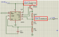
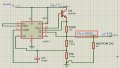
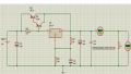
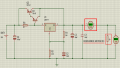
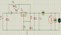
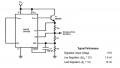
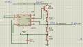
Good evening, I'm new to the forum, I'm writing here on this issue about the LM723 regulator because I have the same problem manipulating the voltage but not the current, I'm designing a voltage regulation source at 15V but I want to limit the current to 1A . In the images I show the diagram of the datasheet and another one that I made in proteus and simulate it.
I am based on the data sheet of LM723, to calculate the voltage at 15V use two resistors, R1 = 7.87 KΩ, R2 = 7.15KΩ, also using a voltage Reference Vref = 7.15V and applying the following equation:

Vout= (Vref)(R1+R2/R2)
Vout = (7.15v)(7.87+7.15/t.15)
Vout= 15.

But my question is the following, since I want a current of 1A and Vsense = 0.7 V, in the data sheet it tells us that the current limit is given by the following equation:

Ilimit = Vsense/Rsc
Then clearing we have:
Rsc= Vsense/Ilimit

And replacing values has a resistance of 0.70Ω, but because when simulating it in software proteus does not give those currents and gives me strange values in I1 and I2, is that my doubt?

And last thing, replace the 2N4898 transistor with a 2n3055 because the software does not handle that transistor.
I hope you woud help me with this question or give me some recommendations.
 

Attachments

Thread Starter

Roberto Rmz

Joined Mar 21, 2018
10
thank you Ian Rogers, I understood a little more.Ian and that you recommend me so that 1 A or 1.5 A can be maintained with a resistance of 50 Ohms to be able to move a step motor of 5 V
Because if I raise the value of the resistance I get 0.300 mA, how can I keep it ??

These are the engines that I want to make work:
28BYJ-48 -5v Steeper engine
 

Attachments

Ian Rogers

Joined Dec 12, 2012
1,136
Okay... The load will contain resistance and reactance.. If you have 15v @ 1A load the total resistance should be 15 ohm..
If your load reduces to 50 ohm then 15V ( doesn't change until current limit ) across a 50 ohm load will be 300mA

You seem to be under so misconception that because the LM723 outputs 15v at 1A it will do no matter what load you have.. The LM723 can deliver up to 1A without current a limit If your load is 30 ohms the current will be 0.5A.. end of..
 

Thread Starter

Roberto Rmz

Joined Mar 21, 2018
10
I already understood what you meant, if you are right, the current with a load of 50 Ohms is reduced to 0.300 mA, but I read in the data sheet that the LM723 can increase up to 10 A by adding external transistors.

By chance you will know about biobliography or some reference where you can investigate some part to be able to add external transistors and increase the current of 0.300 mA to current of 1A or 1.5A.I am still unaware of this topic, and many thanks Ian for the attention.
 

Thread Starter

Roberto Rmz

Joined Mar 21, 2018
10
thanks Dodgydave, I will simulate it with the transistor that you told me and I will read more about transistors because I still have that doubt, about how to increase from 0.300 mA to 1 o1.5A.
 

Dodgydave

Joined Jun 22, 2012
11,285
The circuit i posted uses a pass transistor , this takes any current Over 63mA and leaves the regulator to control the output voltage . Current under 63mA is taken by the LM317.

You can set the current takeover with the R3 22R resistor, the voltage drop across it is 1.4V,
So I=1.4/R3
 

Thread Starter

Roberto Rmz

Joined Mar 21, 2018
10
I made the circuit and configured R3, with the equation I = 1.4 / R3, what I did was clear R3 and taking as I = 1.5A what is the current I want to obtain and substituting values obtained:

R3 = 1.4 / 1.5
R3 = 0.93

But I still give the output a current of 0.300 A with a load of 50 Ohms that is a DC motor that I will use.So I've been reading about connecting transistors in parallel to increase the current but I still do not understand it well.
 

Attachments

Dodgydave

Joined Jun 22, 2012
11,285
I made the circuit and configured R3, with the equation I = 1.4 / R3, what I did was clear R3 and taking as I = 1.5A what is the current I want to obtain and substituting values obtained:

R3 = 1.4 / 1.5
R3 = 0.93

But I still give the output a current of 0.300 A with a load of 50 Ohms that is a DC motor that I will use.So I've been reading about connecting transistors in parallel to increase the current but I still do not understand it well.
No you have got the wrong value for R3, the transistor will only turn on at 1.5Amps, you need it to turn on at a lower current so the regulator wont get hot as it now passes all current under 1.5 amps,.

Increase R3 to 22 ohms as i posted or 34ohms, this way the regulator stays cold and safe.
 
Last edited:

Thread Starter

Roberto Rmz

Joined Mar 21, 2018
10
I still get the same current of 0.300 mA.

A Dodgydave question, if it is ok the way I am interpreting a 5V DC motor, I put it as a resistance and I put the value of 50 Ohms because it was the value that came in the dataSheet. thank you very much and apologize for the questions, I'm just starting with the electronics
 

Attachments

Ian Rogers

Joined Dec 12, 2012
1,136
Doesn't matter how much amps you have available A 50 ohm load at 15V will always be 300mA

V = I*R. If your load was 10 ohms at 15V it would be 1.5A.. If your load was 75 ohms at 15V it would be200mA..
 

Dodgydave

Joined Jun 22, 2012
11,285
I still get the same current of 0.300 mA.

A Dodgydave question, if it is ok the way I am interpreting a 5V DC motor, I put it as a resistance and I put the value of 50 Ohms because it was the value that came in the dataSheet. thank you very much and apologize for the questions, I'm just starting with the electronics
You're getting confused here with your current in your load of 50 ohms and the setting of the Pass transistor.

Your 300mA is the current that your motor will take on a 15V supply simple Ohms Law I =V/R right,. .

So if you want to drive a 10ohms load on 15V then it will take 1.5Amps ok.

This would be too much current for your Lm317 to handle, so we use a Pass transistor to take all the Heavy current, and to work that out it's the same formula Ohms Law,

where the Voltage drop across R3 is that of the transistor to turn on and the current is the Maximum you want the Regulator to take!! the rest is taken by the Pass Transistor, hope this helps you .
 
Last edited:

Thread Starter

Roberto Rmz

Joined Mar 21, 2018
10
If so, I was confused with the R4 resistor and the Dc Motor load. I thought that the 50 Ohm in R4 already simulated the resistance load of the motor.

Already in the proteus I connect the DC Motor and in the properties of the motor I put the load resistance to be 50Ω and in the simulation I already get an approximate of 1.5A.
 

Attachments

Top