Need Help With Identification

Thread Starter

DustinS

Joined Feb 8, 2026
5
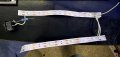
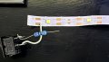
Attached are 2 photos of an L.E.D circuit. The tape is labeled 3v. However, when I tried to verify circuit voltage by sharing the image with Copilot, it kept telling me that it is labeled 5v. Is this an error on behalf of the AI system? If so, can anyone confirm that this circuit should be powered by a 3v - 1.5a supply?
The goal in mind here is to use this L.E.D circuit for a built-in lighting system for my toolbox, and I want to make the unit rechargeable. Any help and or advice is greatly appreciated.
 

Attachments

dl324

Joined Mar 30, 2015
18,216
Welcome to AAC!
The tape is labeled 3v. However, when I tried to verify circuit voltage by sharing the image with Copilot, it kept telling me that it is labeled 5v. Is this an error on behalf of the AI system?
I'd trust your (my) eyes more than an AI.
If so, can anyone confirm that this circuit should be powered by a 3v - 1.5a supply?
It depends on the current needed for each LED. For 8 LEDs, 1.5A would likely be sufficient.

What is the (looks like 10 ohm) resistor for?
The goal in mind here is to use this L.E.D circuit for a built-in lighting system for my toolbox, and I want to make the unit rechargeable.
Do you have a battery chemistry in mind? Lithium-ion are going to be around 4.2V, NiMh/NiCd will be 1.4-1.5V fully charged but will drop to 1.2V. So, you're not going to get 3V from a rechargeable battery.
 

panic mode

Joined Oct 10, 2011
4,864
illumination LEDs in that form factor typically are rated for up to 150mA with forward drop of 3V. the strip shows no sign of any current limiting so 3V is the voltage to use. note, even very slight change in voltage will result in dramatically higher or lower current. since there is nothing to dissipate heat, you probably want to keep current below 100mA (say 60-70mA per LED).
since you have 8 LEDs there, 65mA * 8 = 520mA. if you are ging to power the strip from 5V supply. add series resistor such as 3.9 Ohm 2W
 

MisterBill2

Joined Jan 23, 2018
27,159
illumination LEDs in that form factor typically are rated for up to 150mA with forward drop of 3V. the strip shows no sign of any current limiting so 3V is the voltage to use. note, even very slight change in voltage will result in dramatically higher or lower current. since there is nothing to dissipate heat, you probably want to keep current below 100mA (say 60-70mA per LED).
since you have 8 LEDs there, 65mA * 8 = 520mA. if you are ging to power the strip from 5V supply. add series resistor such as 3.9 Ohm 2W
P.M. is totally correct!! And what does some bit of software that is supposed to recognize images know?? So simply connect a variable low voltage DC supply, using the correct polarity and adjust the voltage slowly and carefully until the LEDs illuminate. Then measure the voltage at that point. Then increase the voltage to 3 volt sand check the current . You will find that P.M. was very close!.
I am not familiar with "Copilot", but I doubt that any image recognition software like that is accurate. Consider that it did not even read the marking on the strip.
So please let us know what you actually see when you test the strip.
 
Last edited:

Thread Starter

DustinS

Joined Feb 8, 2026
5
Welcome to AAC!
I'd trust your (my) eyes more than an AI.
It depends on the current needed for each LED. For 8 LEDs, 1.5A would likely be sufficient.

What is the (looks like 10 ohm) resistor for?
Do you have a battery chemistry in mind? Lithium-ion are going to be around 4.2V, NiMh/NiCd will be 1.4-1.5V fully charged but will drop to 1.2V. So, you're not going to get 3V from a rechargeable battery.
Thanks for the welcome!
The resistor was already a part of the LED circuit that I'm repurposing. I pulled it out of a cheap light-up message board.
As far as the battery system goes, I'm still looking into that. I'm fairly new to the field of electrical circuit design. I don't have any job-related experience nor schooling. Time-consuming, but I have realized that I love the work and problem-solving.
Based upon your statement about the battery system, do you recommend making it a plug-in unit or a replaceable battery set-up?
 

Thread Starter

DustinS

Joined Feb 8, 2026
5
illumination LEDs in that form factor typically are rated for up to 150mA with forward drop of 3V. the strip shows no sign of any current limiting so 3V is the voltage to use. note, even very slight change in voltage will result in dramatically higher or lower current. since there is nothing to dissipate heat, you probably want to keep current below 100mA (say 60-70mA per LED).
since you have 8 LEDs there, 65mA * 8 = 520mA. if you are ging to power the strip from 5V supply. add series resistor such as 3.9 Ohm 2W
Thanks for that rundown! I'm a total newbie in the field, so I'm still learning a lot.
 

Thread Starter

DustinS

Joined Feb 8, 2026
5
P.M. is totally correct!! And what does some bit of software that is supposed to recognize images know?? So simply connect a variable low voltage DC supply, using the correct polarity and adjust the voltage slowly and carefully until the LEDs illuminate. Then measure the voltage at that point. Then increase the voltage to 3 volt sand check the current . You will find that P.M. was very close!.
I am not familiar with "Copilot", but I doubt that any image recognition software like that is accurate. Consider that it did not even read the marking on the strip.
So please let us know what you actually see when you test the strip.
I couldn't agree more. I simply use the software to help search for information when I find it hard to find anything manually.
I will be working on it some more tonight and will certainly share my findings with all of you as well. Thank you all for the help!
 

dl324

Joined Mar 30, 2015
18,216
The resistor was already a part of the LED circuit that I'm repurposing
That gives you some leeway regarding operating voltage.
Based upon your statement about the battery system, do you recommend making it a plug-in unit or a replaceable battery set-up?
Is the toolbox portable or stationary? If it's portable, battery operated would make more sense.
 

panic mode

Joined Oct 10, 2011
4,864
If so, can anyone confirm that this circuit should be powered by a 3v - 1.5a supply?
yes you can power this circuit from such PSU. 1.5A should be plenty to run all LEDs even at their likely rated value (150mA per LED). but that would require heatsink. without heatsink, i would say 65mA per LED is plenty. if you have not powered it before and if your PSU has any adjustment, set it a bit lower at first (such as 2.8V) or consider using resistor (0.39 Ohm 1W) or longer wires.
 

B-JoJo-S

Joined Jan 3, 2026
208
the strip shows no sign of any current limiting so 3V is the voltage to use.
yes you can power this circuit from such PSU. 1.5A should be plenty to run all LEDs even at their likely rated value (150mA per LED).
The one thing that would worry me is how the LED's are wired on the strips. Are they all in parallel? If so then they should each have their own resistor. If they're in series then a single resistor would work. But in series the voltage is going to have to be higher than 3 volts. If 3V is 3Vf (volts forward) and eight in series then you'd need 24 volts. But at 24V you won't have any current control. If they are wired in groups of 4 then 12 volts would be needed. But don't jump to testing with high voltages, not until you know what voltage is needed. @MisterBill2 has the right plan, start very low and gradually increase the voltage until you get the desired illumination. Keep in mind you can over-do it with voltage. Too much voltage and you'll blow something out.

How do we know the LED's are 150mA per LED? I must have missed something.
 

panic mode

Joined Oct 10, 2011
4,864
it is called experience i thought i already mentioned how i got the numbers. and that is not just my idea, if you check likes, you will notice that others also agree.

so let's do a detailed breakdown:

indicator LEDs typically are good for 20mA and sweetspot is 5-10mA.

high efficiency indicator LEDs are usually happy with 1mA or so.

illumination LEDs in that form factor (single diode) are usually rated for 150mA but will scream and die flaming death if there is no heatsink. for operation without heatsink it is normal to keep the current at 60-65mA.

then there are COBs, they are single package with many illumination LEDs inside. depending on the configuration they can have different voltage/current requirements. they always require massive heatsinks.

shape of LEDs (and larger package) clearly shows that what you have is a group of individual illumination LEDs.

since the strip is labeled "3V" they must be all in parallel and without resistor. parallel circuits allow making LED strips that can be cut to length. in this case entire single circuit is - one LED. in other cases it may be branch of 3 LEDs and resistor connected in series. then entire strip is just bunch of those branches in parallel. to prevent cuts in wrong place (and have some LEDs not working) such strips have printed marks "cut here". your strips do not have that.

strips designed to have many LEDs always have some sort of current limiting - there is an obvious SMD resistor near each LED or some LED driver IC. i see no sign of any of that so your LEDs are what i have already described - simple LEDs wired all in parallel and without series resistors. you can confirm that by doing continuity check (touch DMM probes to solder pads of different LEDs).

to be really sure that above speculation is correct, you can use lab power supply and slowly increase voltage until you can feel LEDs getting warm. then read displayed voltage and current on the supply itself and find smaller PSU to power them.
 

B-JoJo-S

Joined Jan 3, 2026
208
it may be branch of 3 LEDs and resistor connected in series.
This is the sort I'm familiar with. And it runs on 12VDC. Current limiting is done by one resistor limiting current to a series of 3 LED's. I've never seen any other sort of strip. Actually, yes, I have. Addressable LED's. But that's a different animal than what we're discussing.
 

panic mode

Joined Oct 10, 2011
4,864
correct... it really boils down to just few types.

i have seen also LED strings on tiny wires - also all in parallel. this makes it hard to control. one led goes out and rest fails one after another - domino style. that is why it is found in cheapest of things. the only way to prevent that is to use precise voltage regulation which would increase the cost.

i just dug out one of the project - the models I used most recently was HL-A-2835D46W-S1-08-HR3. there is tons of LEDs in same or similar form factor and for most of them, V/I specs are pretty similar a well.
 

B-JoJo-S

Joined Jan 3, 2026
208
You can't beat experience.

EDIT: Are those the same as what's in 120 volt LED lamps? I believe I've seen an LED lamp that failed pulled apart.
 
Last edited:

Thread Starter

DustinS

Joined Feb 8, 2026
5
The one thing that would worry me is how the LED's are wired on the strips. Are they all in parallel? If so then they should each have their own resistor. If they're in series then a single resistor would work. But in series the voltage is going to have to be higher than 3 volts. If 3V is 3Vf (volts forward) and eight in series then you'd need 24 volts. But at 24V you won't have any current control. If they are wired in groups of 4 then 12 volts would be needed. But don't jump to testing with high voltages, not until you know what voltage is needed. @MisterBill2 has the right plan, start very low and gradually increase the voltage until you get the desired illumination. Keep in mind you can over-do it with voltage. Too much voltage and you'll blow something out.

How do we know the LED's are 150mA per LED? I must have missed something.
"Are they all in parallel?" It appears to me that they are in parallel. 2 strips of 4 LED's in parallel and it had one resistor in seires when salvaged them.
 
Top