 Facebook
 Google
 GitHub
 Linkedin
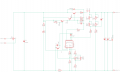
Hello, I built the power supply from the attached schematic, but it does not work.
I found that the output voltage stays at about 3.5V at any position of the potentiometer POT3 or POT1.
I also found that the voltage across BE junction of the BC transistor stays always at 0.55-0.60V.
The input voltage is about 33Vdc, and I am using a 24Vac / 160VA transformer. I used TIP35C instead of BD249, and BD140 instead of BD136.
I checked the layout and it seems to be ok (no bridges). I used only POT1, POT2 and POT3.
The original schematic is named original_schematic and the schematic I build is named schematic_img.
Between the schematic that I built and the original schematic is the following difference: the schematic that I built is using an external transistor for current limiting, because I found some time ago that the internal limiting transistor is very weak and it does not resist when there is a short circuit on the output, probably because the current that suddenly flown through it is very high. Or probably I am using some fake LM723.
I tried the following: I changed the potentiometers with some new ones, I changed LM723 with a new one, but the situation is the same.
What should I check to find were is the problem ?
I think that there is a problem with the current limit, but I am not 100% sure.
Later Edit: The voltage on pin 12 is about 33V, on pin 11 is about 32.5V, on the output pin (pin 10) the voltage is always 4.1V.
Attachments
-
 112.8 KB Views: 86
 -
 64.4 KB Views: 85
Last edited:


