 Facebook
 Google
 GitHub
 Linkedin
Hello everyone!
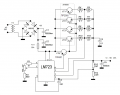
Currently I am trying to build a power supply unit using LM723 chip. I have a transformer that is rated at 18 V and 30 Amps and after connecting a bridge rectifier and a capacitor I got around 25 volts DC. While the transformer is rated at 30 amps, in real life it would give out arond 20 amps for sure. So, the input numbers are 25 volts and 20 amps DC. To handle that much current I need to use a number of pass transistors and I am planning to use TIP2955 for that. However, they're PNP transistors and all the circuits I was able to find on the internet and even in manufacturers' datasheets have NPN TIP3055 transistors. I have attached a picture of such a circuit that best suits my needs and so that, you guys could understand my question.
Will the power supply unit work if I replace TIP3055 transistors with TIP2955 transistors? Since these two types of transistors are of opposite polarity, is it going to be enough if I just swap the polarity, i.e. connect the emitters of TIP2955 to the input via balancing resistors and keep the rest of the circuit unchanged? In the attached picture you can see that I've replaced first of the transistors VT1 to TIP2955 and driver transistor VT5 to TIP42C as an example.
Attachments
-
 28.2 KB Views: 25


