Just some general questions about remaking something from the past

Status
Not open for further replies.

Thread Starter

Berzerker

Joined Jul 29, 2018
623
MisterBill said:
The transformers are not that hard to copy, I have wound transistor output transformers "close enough" to work well and sound OK. And if he wants to make a bunch of them there are companies that can produce as many as he can pay for within 15 miles of my house. Osborne is one of them.
Thanks MisterBill. I did post earlier about finding a place that would custom wind them for me but I haven't contacted them (yet).
http://www.merrenaudio.com/
I was hoping to find someone closer to where I live but I don't think that is going to be the case. Yes there are alot of them.
MisterBill said:
Circuit boards of that era were not so fine-line and complex. Making a copy to send to a China board house and for a hundred single sided boards probably $5 each or less, if no solder mask and no plated through holes, maybe $3 each.
This I have kinda looked into to. I also have all the components picked out with close enough specs or better but (two) and those are the transformers. If I had those I could put everything on a breadboard and begin testing. I think I'll spend some of today getting quotes from some of these places.
MisterBill said:
It is easy to get 25 watts of audio from a 12 volt push-pull transformer output amplifier if you use good transistors and drive them with a decent (copied) driver transformer.
Now that's encouraging.
MisterBill said:
A production run of 100 units would run just a few thousand dollars. Then comes what I see would be the really big problem: Nobody would want them.
I wouldn't be so quick to say that. In my searching and reading there are still people out there that ask for schematics or components for these.
 

Audioguru

Joined Dec 20, 2007
11,248
Which Darlington part number have you "picked out"? Did you calculate the peak current for them which is determined by the peak power into a 4 ohms speaker and the turns ratio of the output transformer?

With TIP140 10A Darlington transistors, if the peak current is 8A then 26.4V p-p gives 53 real watts! If the output transformer is huge, heavy and expensive then its output can be 45 real Watts or 90 fake Whats! Some 6" x 9" car speakers can survive 45 real Watts.

If my math is correct (I have never designed an amplifier with an output transformer) then tell the transformer manufacturer the center-tapped primary gets a maximum of 9.3V RMS and a maximum current of 5.7A RMS for 53W. The secondary feeds a 4 ohms speaker with whatever frequency response you specify. 20 to 20kHz plus and minus 3dB is hifi, 300 to 3kHz plus 5dB and minus 15dB is old fashioned telephone lack of fidelity (hello, I didn't understand what you said, please repeat it). Low frequencies at high power makes a transformer big and expensive. The 6" x 9" speakers in a car cannot produce frequencies below about 50Hz so the transformer can be smaller and cheaper if it cuts below 50Hz. Boom boom bass is about 80Hz to 120Hz so some people will like it.
 

Thread Starter

Berzerker

Joined Jul 29, 2018
623
Just a couple of my choices. I have a few more picked out and would have asked here before making a final decision.
The Darlington transistors;
https://www.digikey.com/product-detail/en/sanken/2SD2081/2SD2081-ND/3929435
https://www.digikey.com/product-detail/en/sanken/2SB1259/2SB1259-ND/3929426
AG said:
With TIP140 10A Darlington transistors, if the peak current is 8A then 26.4V p-p gives 53 real watts! If the output transformer is huge, heavy and expensive then its output can be 45 real Watts or 90 fake Whats! Some 6" x 9" car speakers can survive 45 real Watts.
"WOW" AG you could have told me this 100 posts ago.
AG said:
If my math is correct (I have never designed an amplifier with an output transformer) then tell the transformer manufacturer the center-tapped primary gets a maximum of 9.3V RMS and a maximum current of 5.7A RMS for 53W. The secondary feeds a 4 ohms speaker with whatever frequency response you specify. 20 to 20kHz plus and minus 3dB is hifi, 300 to 3kHz plus 5dB and minus 15dB is old fashioned telephone lack of fidelity (hello, I didn't understand what you said, please repeat it). Low frequencies at high power makes a transformer big and expensive. The 6" x 9" speakers in a car cannot produce frequencies below about 50Hz so the transformer can be smaller and cheaper if it cuts below 50Hz. Boom boom bass is about 80Hz to 120Hz so some people will like it.
"Thank you AG" but again you could have told me this and I could have seen if they still make one with close to those specs 10 days or so ago.
See even you admit I can get a few more Watts than 15 out of it (?)
Had a small set back my phone just died, won't charge, won't boot up, Nothing, so I had to buy a new one and just got back and letting it boot up so I can set it up. I like talking to people in person so I want to call them.
 
Last edited:

Audioguru

Joined Dec 20, 2007
11,248
You found Sanken (Japanese) darlingtons. One is P-channel that needs a complete re-design of the amplifier.
They are in a package that has its metal back insulated so the absolute max heating is only 30W in an air-conditioned room with an infinite (impossible) heatsink. No good.
The TIP140 American darlington I recommended has a max allowed heating of 125W so a reasonable size of a heatsink can be used for lots of output power.

The output power is Voltage times Current. The output transformer boosts the voltage and the darlingtons boost the current. Both must be able to handle the power. The original custom-made Mindblower with the center-tapped voice coil had a max output power of about 21W which many people will say sounds as loud as a modern 15W car amplifier.
Today, nobody makes the special output transformer you need.
 

Thread Starter

Berzerker

Joined Jul 29, 2018
623
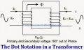
I wanted to ask a couple of questions about diptrace. I've been looking under transformers and you all have seen the pic of the input transformer and as I said it only has four wires. when you look at the Mindblower schematic if I'm to pick the correct one to place in the schematic the dots show the beginning and end of that wire (right)? If I want to add my own custom symbol I have to make it up and then place it in my folder (I also create) Right? I haven't found one with the dots yet on the same side. Now again does it simulate voltage going through it or just show un-attached wires and components. In other words can it test it without actually putting the parts together and having one melt down?
 

ebeowulf17

Joined Aug 12, 2014
3,307
I wanted to ask a couple of questions about diptrace. I've been looking under transformers and you all have seen the pic of the input transformer and as I said it only has four wires. when you look at the Mindblower schematic if I'm to pick the correct one to place in the schematic the dots show the beginning and end of that wire (right)? If I want to add my own custom symbol I have to make it up and then place it in my folder (I also create) Right? I haven't found one with the dots yet on the same side. Now again does it simulate voltage going through it or just show un-attached wires and components. In other words can it test it without actually putting the parts together and having one melt down?
DipTrace doesn't have any simulation capabilities. Most (or at least many) of the users here use LTspice for simulations. It's totally free and very powerful.

Unfortunately, it's mostly full of LT parts, so if you're wanting to simulate parts from other manufacturers, you have to find them elsewhere, import them, etc. When you're just trying to understand basic flow and functionality, you can often fake it with the closest matching LT part, but if you really want parts-specific sim results then it's a bit more work.

Not sure about the dot placement question. Sorry.
 

Thread Starter

Berzerker

Joined Jul 29, 2018
623
@MisterBill
MisterBill said:
Osborne is one of them.
Could you please insert a link? I contacted Merren and I don't know if I would use them (?) sounded like Cheech and Chong "if you catch my drift". That's why I like to talk to someone. He coughed the whole time again you know what I mean. Must have been some good Sh.... Stuff.
Website makes him look big but I bet he's a guy with a garage.
 
Last edited:

Audioguru

Joined Dec 20, 2007
11,248
The darlingtons will not be biased correctly if the secondary of the input transformer does not have a center-tap as its 5th wire.
 

Thread Starter

Berzerker

Joined Jul 29, 2018
623
AG said:
The darlingtons will not be biased correctly if the secondary of the input transformer does not have a center-tap as its 5th wire.
But the original only had four wires. And they do connect to the ground. I'm still trying to wrap my mind how it's a input transformer and not an isolation transformer. Put in your mind a transformer (only four wires) one end wire of each are connected to the each of the bases on each of the transistors and then the middle two are tied together and go to ground. You can't ground a input transformer that way "Can you"? A input transformer needs two input wires and two output wires "correct"? Why would you attach them to a ground.
 

Audioguru

Joined Dec 20, 2007
11,248
The diodes and a resistor to +12V connect to the center-tap on the secondary winding of the input transformer to bias the bases of both Darlington transistors at +1.4V. If the center-tap is missing then the diodes and resistor are not needed and current in the darlingtons floats all over the place and the output signals from the darlingtons will be erratic. Measure continuity between the bases of the darlingtons (they connect to the secondary winding of the input transformer) and the junction of the resistor and the anode of one of the diodes. They should be connected together. Measure again to see if the bases are grounded through the transformer. They should not be grounded.

No wire on the input transformer is grounded. Its metal frame might be grounded.
Your idea of twisting together the secondary wires and grounding both of them eliminates the bias voltage on the darlingtons bases which would produce severe crossover distortion:
 

Attachments

Thread Starter

Berzerker

Joined Jul 29, 2018
623
I don't want to keep posting the same pic over so here's the link. post #192
https://forum.allaboutcircuits.com/...making-something-from-the-past.150844/page-10
There are only has six wires on the whole board. #3 on that pic goes to the base of one of the transistors, #4 goes straight into the output transformer back out of it and goes in the second transistors base and 5 is GRN. The audio input wires attach right where 3 and 4 are. There are no input wires on the transformer itself. I see what your saying AG but it's me that it doesn't make sense too. post #204 shows the transformer (?) and if input wires were attached to it they would attach straight on the outside two wires. #5 (IS) GRN.
@AG
TIP140 transistor, Part status: obsolete
 
Last edited:

Audioguru

Joined Dec 20, 2007
11,248
If the input transformer has no input wires then it is not needed and the darlingtons will float all over the place being erratic and probably damaged.
Since the input transformer has no center-tap on its secondary then the resistor and two diodes that prevent crossover distortion are also not needed. Then the severe crossover distortion will sound awful.

Go to Digikey and look at their TIP140 darlingtons in the nice new higher power package. The old small lower power package is obsolete.
Texas Instruments invented the TIP line of transistors and might not make the TIP140 any more. Today ON Semi make them. ON Semi is the new name for Motorola.

I did not look at Digikey far enough. The TIP141 and TIP142 10A darlingtons cost less, are made by ON Semi and ST Micro and have a higher maximum voltage. There are also many of these ones in stock.
 

Thread Starter

Berzerker

Joined Jul 29, 2018
623
Last edited:

Thread Starter

Berzerker

Joined Jul 29, 2018
623
Capacitor markings question (?) sources:
https://www.wikihow.com/Read-a-Capacitor
http://grathio.com/assets/capacitor_tags.pdf
http://www.robotoid.com/appnotes/electronics-capacitor-markings.html
Capacitor reads ZSF 150 20%
If you look at one page it tells you one thing and the others another. one says the 150 stands for 15uf the other gives it a value of 1,000,000.
the Z one says +80% -20% while the capacitor only has 20% on it. haven't found any thing on S yet. F on one of them is + or - 1%. or it might just stand for farad. just asking.
 

ebeowulf17

Joined Aug 12, 2014
3,307
The audio input wires attach right where 3 and 4 are. There are no input wires on the transformer itself.
This is just a wild guess, but I may have an explanation for the confusing input transformer wiring.

If you didn't need the galvanic isolation that a transformer provides, you could have the board input wires directly driving one side of the circuit, and use a simple 1:1 transformer as an inverter to drive the other side.

In that case, the two twisted wires would be common with each other, presumably grounded. One of the loose wires would be the input, relative to ground. And the other loose wire would be output, an inverted copy of the input, referenced to ground.

This configuration would provide the same pair of signals as the center tapped transformer, but without the isolation.

upload_2018-8-22_9-18-55.jpeg
In the diagram above, imagine the two lower wires are twisted together and both go to ground. The top left wire is the board input, which is also the input signal for one of the Darlingtons, and the top right wire is the inverted transformer output, which is the input signal for the other Darlington.

I'm not entirely sure if this concept makes sense in theoretical terms, but my gut says it's plausible.

As for whether or not that's what you've got in your circuit, I have absolutely no idea. I'm no good at reverse engineering things remotely. I'd have a better chance in person, but no guarantees even then! So I'm just throwing ideas out to see if anything sticks!
 

Audioguru

Joined Dec 20, 2007
11,248
PNP and NPN push-pull Darlington transistors are used in a completely different circuit. The circuit will have a power output of about 2.8W into a 4 ohm speaker with fairly low distortion and a 14.4V supply. It and almost any amplifier can drive a transformer for higher power.

The TIP147 Darlington you found is in an old package that has low maximum allowed power. A more powerful package is available.
You also found a TIP142 in an old low power package. A more powerful package is also available.

Google says old capacitors were marked "Z5F" to show that they were ceramic type. Yours is either 15pF or 150pF. 0.1uF (100,000pF) is the largest old ceramic capacitor I have ever seen.

If you use the completely different NPN and PNP transistors circuit then you don't need to invert the input signal, then an expensive input transformer is not needed. A little transistor can be used for voltage gain. But you might as well use a modern IC power amplifier to replace the little transistor and the two darlingtons.
 

Thread Starter

Berzerker

Joined Jul 29, 2018
623
AG said:
But you might as well use a modern IC power amplifier to replace the little transistor and the two darlingtons.
I posted one of these before. Of course it was the wrong type but I thought you would know what I meant. Never spec'd one out but I will start looking at them closer. the more I look at what I got now I think their both NPN, just the way things are hooked up.
@ebeowulf
I think you might be on to something (?). I've been looking at a few other things on it and about it today. Plus been doing some diptrace, No drawing of NPN or PNP so when you convert to PCB it hangs up. Searching for pics to put in it.
AG said:
Google says old capacitors were marked "Z5F" to show that they were ceramic type. Yours is either 15pF or 150pF. 0.1uF (100,000pF) is the largest old ceramic capacitor I have ever seen.
They aren't much so I'll get a few of each for testing.
AG said:
The TIP147 Darlington you found is in an old package that has low maximum allowed power. A more powerful package is available.
You also found a TIP142 in an old low power package. A more powerful package is also available.
So the other two were good then (YES)? They all had the specs of the one you posted or better.
 
Last edited:

Audioguru

Joined Dec 20, 2007
11,248
I look at the schematic from the manufacturer, not a rusted old product that might have been repaired wrong and does not work.
Your MindBlower speaker might have a replacement transformer on it that never had the important center-tap or its center-tap wire rusted away.
 

Thread Starter

Berzerker

Joined Jul 29, 2018
623
No AG I have two of them and they are both are the same way. Only four wires and they both have been in a box taped up all these years. I didn't know what was in the box is how I found them. They were bought new and I blew the speakers up and the copper wires in between a few of the components fried (not that part) like in between the diodes and capacitors and a diode popped is why I took them out. Plus they had closed the facility where I'm at so no replacement parts.
Edit: one place I called $85 an hour to re-wind a transformer. still looking.
 
Last edited:

Thread Starter

Berzerker

Joined Jul 29, 2018
623
Trying to get my mind on Ohms law and how to calculate it myself. was looking at an single channel IC chip datasheet and it says 40W on a 8 ohm load from 25V. Knowing (V) is for volts, (I) is current or amps and (R) is resistance or ohms . looking at the ohms law pyramid they say if you have any two you can find the others easily. Volts is on top divided by either of the other two to get the others value. The (I) and (R) are across so you times them.
let's start from the obvious 25V.
25V / 8 ohms = 3.125 amps
where do you go from here to get 40W
and google says to get watts times volts and amps 25 x 3.125 = 78.125
 
Last edited:
Status
Not open for further replies.
Top