Just some general questions about remaking something from the past

Status
Not open for further replies.

Thread Starter

Berzerker

Joined Jul 29, 2018
623
Dual supply voltage question. Google says
google said:
If you see a dual-supply or dual-voltage op amp, it means that two supply voltages power the amplifier; the absolute supply voltage levels are the same, except one is negative and swings below 0 V, and the other supply voltage is positive and swings above 0 V. “Single-supply” op amps came later on and are more …
Also read this:
https://www.quora.com/Why-does-an-operational-amplifier-need-two-power-supplies
above said:
Operational amplifiers have two power supply rails because they usually need to swing bipolar - output voltages that go either positive or negative in response to the normal range of input signals. Usually the signals in an operational amplifier are relative to a ground that is somewhere between the two rails, thus the plus supply and minus supply are usually, but not always, symmetrical about ground.

Without the dual supplies the output signal would clip at the ground potential.

If you look at a pinout connection diagram for a standard opamp you will notice there is no ground terminal pin at all. Thus the opamp only needs the voltage between the positive rail and the negative rail to work which could be supplied by a single power supply equal to the sum. But usually circuits usually need a ground reference and so the opamps are described as having two power supplies.
So the above converter won't work right?
Edit: also found you can't get over 45W on a 12VDC power supply.
Edit 2: found out what a dual supply was on the IC I was looking at and it was VAC in.
 
Last edited:

Audioguru

Joined Dec 20, 2007
11,248
The new voltage boost converter you found has a max output of 75W and 6A.
With a 30V supply, a single linear amplifier has an output of 23W and heating of about 18W for a total power from the converter of 41W.
The power and current are fine for this voltage converter. The converter operates at a frequency above what is audible and its burst mode can be turned off.

If the amplifier is bridged and the speaker is 4 ohms then 30V is too high for its power supply voltage because its output will try to be 85W.
 

Thread Starter

Berzerker

Joined Jul 29, 2018
623
AG said:
The power and current are fine for this voltage converter. The converter operates at a frequency above what is audible and its burst mode can be turned off.
OK Who are you and what have you done with the real AG? AG would never say anything good about anything I posted... ;)…..:D
Thanks AG. I spent most of my day yesterday trying to learn Diptrace again. I got ok in the component editor but now I'm trying to learn the pattern editor. It's look at tutorial come back to Diptrace, mess up go back to tutorial, come back to Diptrace, mess up. Can't figure out how you turn on dimensioning to show the dimensions between holes in free hand. Or what if you want to lay your component down instead of have it stand up. I'll get it.
AG said:
They play with the numbers. With a 16V supply its output into 4 ohms is 22W at low distortion or 45W when its has extreme clipping distortion that nobody wants to hear.
Yea I seen the anti clipping mode thingy on the datasheet and then there's another thing I put in my notebook to look up. I also was reading the datasheet and ran out of time yesterday to finish about the MUTE having something to do with the biasing of the chip. "Now don't say anything bad AG, I did say I didn't get to finish".
They give a little schematic I guess to show you what all you would need to make it work(?) But they only give you values. How does someone tell if it's Aluminum Electrolytic or Ceramic if it's a capacitor?
shortbus said:
Berzerker, Don't look at the ones that are adds for a store, but look at some of the circuits in this Google. you may find something that will do what you're wanting. Then you just put it in a box like a Mindblower.
Without having to learn right off the bat how to design one of these too, I figured I could buy one and see if it was cheaper that way or buy the parts and just rearrange them on my own board. I don't think you can copyright the use of the same components but the board is a different story.
 
Last edited:

Audioguru

Joined Dec 20, 2007
11,248
Now that you are talking about making a 30W amplifier I forgot to remind you how it will sound.
It will sound only slightly louder than a 15W normal modern car radio amplifer, so why bother making it.
Our hearing's sensitivity to loudness is logarithmic, like the matching logarithmic volume controls we use. Then 10 times the power sounds twice as loud.

Another problem with your idea is that car radios have 4 channels, yours has only 1 and its voltage booster can drive only 1.
Another problem is how will you turn on its power and turn off its power?
 

Audioguru

Joined Dec 20, 2007
11,248
How does someone tell if it's Aluminum Electrolytic or Ceramic if it's a capacitor?
An aluminum electrolytic capacitor filters and passes very low frequencies well and have extremely high values if you need it. It has inductance which causes it to be poor at radio frequencies.
A ceramic capacitor filters and passes radio frequencies well, has low values, is microphonic (make noise if bumped or rattled and it changes its value with voltage which causes low frequency distortion.
A film capacitor passes audio with extremely low distortion but very high values are not available.

Some capacitors in an audio amplifier circuit are used to prevent high frequency oscillation then a ceramic capacitor must be used because many audio amplifiers have a frequency response that reaches radio frequencies. Ceramic capacitors are also used to filter out radio frequency interference.

The definition of the exaggerated EIAJ power is when a squarewave is used as the input to an amplifier. A squarewave is full of clipping harmonics to make the power number doubled.
 

Thread Starter

Berzerker

Joined Jul 29, 2018
623
AG said:
Now that you are talking about making a 30W amplifier I forgot to remind you how it will sound.
It will sound only slightly louder than a 15W normal modern car radio amplifer, so why bother making it.
Now it's 45W. remember AG if cars put out 15W and we use "the formula" well that come out to about to 1.76 (close} watts again or 3.513 if a 4ohm speaker is used. I know there's something missing in that formula or there would be no need to even buy an amplifier. I know when you install an amplifier it does make your system louder.
AG said:
Another problem with your idea is that car radios have 4 channels, yours has only 1 and its voltage booster can drive only 1.
You hook one to each channel. from looking at it, it's very small and I would just place one in each speaker just like the Mindblower had one in each of its.
AG said:
Another problem is how will you turn on its power and turn off its power?
One step at a time AG, remember I am a beginner.
Edit: just so you know someone took over your account yesterday and posted something good about me.. You might want to look into that.
Glad to see you back AG.
 
Last edited:

Audioguru

Joined Dec 20, 2007
11,248
Now it's 45W. remember AG if cars put out 15W and we use "the formula" well that come out to about to 1.76 (close} watts again or 3.513 if a 4ohm speaker is used. I know there's something missing in that formula or there would be no need to even buy an amplifier. I know when you install an amplifier it does make your system louder.
You hook one to each channel.
One step at a time AG, remember I am a beginner.
Edit: just so you know someone took over your account yesterday and posted something good about me.. You might want to look into that.
Glad to see you back AG.
The output of a single amplifier is 1.76W with a 12V supply into an 8 ohm speaker, 3.5W into a 4 ohm speaker. With low distortion.
But an ordinary car radio output power is not measured with a 12V almost dead battery, the battery is charging at 14.4V then the power is 5.3W into the normal 4 ohm car speaker.

Ordinary car radio amplifiers are not single, they are bridged then the power with a 14.4V supply into a 4 ohm speaker is more than 15W, maybe 18W.

Adding another amplifier with its own supply voltage booster with an output of only 30W makes only a little more sound level.
The amplifier that produces 45 Whattts at extremely high distortion that nobody wants to hear produces 30 or less real Watts at low distortion that sound good, but it does not sound much louder than the 15 real Watts from an ordinary car radio amplifier.
 

shortbus

Joined Sep 30, 2009
10,049
Without having to learn right off the bat how to design one of these too, I figured I could buy one and see if it was cheaper that way or buy the parts and just rearrange them on my own board. I don't think you can copyright the use of the same components but the board is a different story.
Do you think that everyone making something like this has to create a brand new way of doing it? Amplifiers have been around a long time and they still in the end do the same thing, amplify.

You also can't go too much by what AG is telling you about how people perceive audio. He is one of the few people in the world who can hear "true musical sound", as he has said many times in many forums over the years. What sounds good to you and me would sound terrible to him.


Have you seen this site? Many pages on audio and calculators that may help you.
http://www.sengpielaudio.com/calculator-ohm.htm
And then there is this one that puts things in a different perspective. http://www.sengpielaudio.com/calculator-ak-ohm.htm
 

shortbus

Joined Sep 30, 2009
10,049
I spent most of my day yesterday trying to learn Diptrace again. I got ok in the component editor but now I'm trying to learn the pattern editor. It's look at tutorial come back to Diptrace, mess up go back to tutorial, come back to Diptrace, mess up. Can't figure out how you turn on dimensioning to show the dimensions between holes in free hand. Or what if you want to lay your component down instead of have it stand up. I'll get it.
Again it's just how I do things in Diptrace. Don't know about others.

When I need a new part, first I look for something in the original parts that is in the same "package". There really aren't that many different IC packages so I get what they call it in the data sheet of the part I want to make new and look in Google for parts in that package. Then see if it is in Diptrace.

Then bring it up in the components editor in Diptrace. There is a screen that will then let you both rename the part, and rename the pins of the part. You just need to keep the pin number and pin name the same. Then save the component to "my library". Since you used an existing "pattern"(for a different part) the pattern is already done for you.

Like I said before, I knew nothing about these kinds of programs when I started, and don't know if I'm doing it right. But so far it has worked for me. Hope this helps.
 

Thread Starter

Berzerker

Joined Jul 29, 2018
623
I did it.... I did it

And (ALL) free hand, no templates, just me.
@shortbus
Yea I know he's a little picky and set in his ways (or thinking I should say). Thank You for the calculators I've placed them in my favorites.
shortbus said:
Then bring it up in the components editor in Diptrace. There is a screen that will then let you both rename the part, and rename the pins of the part. You just need to keep the pin number and pin name the same. Then save the component to "my library". Since you used an existing "pattern"(for a different part) the pattern is already done for you.
I made a folder up just for my components, placed it in the library and had a little bit of trouble hunting it down but finally got it to work.
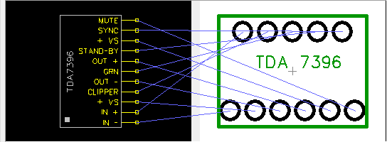
Pattern Editor is what got me. It didn't look like the tuts you see online. Once I found where everything was at I took off.
Edit: I forgot to put my pin 1 (Dot or Square) in the pattern but have corrected it.
Edit 2:
Well, Well, Well, Don't this just throw a wrench into the mix.
 
Last edited:

Audioguru

Joined Dec 20, 2007
11,248
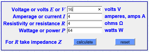
Electric heater:
16 Volts DC power supply.
4 Amperes DC of current.
4 ohms resistor.
Equals 64 Watts of heat, not audio power.

Audio amplifier:
16VDC power supply.
2V output voltage loss, 14V p-p output swing. 14V/2.828= 4.95V RMS output, (4.95V squared)/4 ohms= 6.13 real Watts at low distortion.

Bridged amplifier output= 6.13W x 3.5= 21.5 real Watts at low distortion, or 64 Whattts with lots of horrible distortion.


A sinewave looks smooth on an oscilloscope and sounds like a smooth tone to your ears. A clipping amplifier output has the top and bottom flattened at the voltage as high and as low as it can go. The clipping produces a buzzing kind of tone:
 

Attachments

Thread Starter

Berzerker

Joined Jul 29, 2018
623
If your numbers were true then you would not see the videos where the speaker shreds paper apart online. No amp would ever go above 10W in your formula and I know that's not true. The reason we buy amps is to MAKE our stereos louder. I see a flaw in your formula cos if you look at it at face value no-one would even need an amplifier. and if you put 18V in it comes out to 81W which is the max volts allowed.
AG said:
4 ohms resistor.
Isn't this the load or speaker?
the formula has load or resistance not resistor.
 
Last edited:

Audioguru

Joined Dec 20, 2007
11,248
Elliot Sound Products has many power amplifier designs in the Projects section of his website.
One power amplifier is similar to the one I posted in my last post and it uses an 84V supply to produce 100W into 8 ohms.
Output voltage losses are 4V. (80V p-p) / 2.828= 28.3V RMS. (23.8V RMS squared) / 8 ohms= 100 Watts at low distortion. His formula is the same as my formula.

He has another amplifier that produces 1500W into 4 ohms. He says the same as me that the output voltage swing must be (77.5V RMS squared)/4 ohms= 1501.5W. He says the same as me that the undistorted waveform is 77.5V RMS x 2.828= 219.2V p-p and its currents are so high that the voltage losses are 40V so the power supply is 260V!

Which amplifier uses a max of 18V for its supply and produces 81W? An electric heater does. (18V squared) / 4 ohms = 81W of heat. No audio.
18V RMS can do it. 18V RMS is (18V x 2.828=) 50.9V p-p. If the amplifier has 4V of output voltage losses then it needs a 55VDC power supply.
If the amplifier is perfect and has no voltage losses (impossible) then (18V p-p) / 2.828=) 6.4V RMS. Then the output power is (6.4V squared) / 4 ohms= 10.2W. Bridged its output is 10.2W x 3.5= 35.7 real Watts, or hundreds of Whattts..
 

Thread Starter

Berzerker

Joined Jul 29, 2018
623
You mean we finally got above 10W, amazing.
https://express.google.com/u/0/prod...s&utm_campaign=gsx&utm_content=control_90_MAX
Then you have to put all those converters in your car just to get it to work. I think I will try my idea and just build a set and see what happens(?)
adding up how much it will cost now to do the prototype. Production is a lot less.
Edit: Calculate above with that formula
Edit 2: $82 dollars and that's just looking at one place not looking for the best price, Including speakers. not added: heat plate, plastic cover, extra wire to hook everything up. I might have missed something but I will think about it and add it. around $100 to prototype. Oh PCB board $6.00 for 10
 
Last edited:

Audioguru

Joined Dec 20, 2007
11,248
The Lanzar bridged stereo 2500W RMS per channel amplifier into 4 ohms is crazy for a car.
It is probably a class-D because its size is much too small for cooling a class-AB so its heating is probably 250W. Then its total power is 5250W and its maximum continuous current from the car battery is 5250W/13.2V= 400A. Crazy.

Are you going to use the TDA7396 IC amplifier with a Chinese voltage booster providing 18VDC? Its output power is about 27W into 4 ohms or about 40W into 2 ohms.
 

ebeowulf17

Joined Aug 12, 2014
3,307
Edit 2:
Well, Well, Well, Don't this just throw a wrench into the mix.
I'm sorry to say, but that threw nothing into the mix. We've already discussed the losses inherent in the system, and why simple ohms law calculations don't work when you start with a DC supply voltage and try to calculate AC output wattage.

I already described conceptually what the steps were, and AG fixed my mathematical errors.
 

Thread Starter

Berzerker

Joined Jul 29, 2018
623
AG said:
Are you going to use the TDA7396 IC amplifier with a Chinese voltage booster providing 18VDC? Its output power is about 27W into 4 ohms or about 40W into 2 ohms.
Yes. And in an earlier post it was just fine, what changed?
ebeowulf said:
I'm sorry to say, but that threw nothing into the mix. We've already discussed the losses inherent in the system, and why simple ohms law calculations don't work when you start with a DC supply voltage and try to calculate AC output wattage.

I already described conceptually what the steps were, and AG fixed my mathematical errors.
If you look at AG's post #318 now all of a sudden it's 27W or 40W. if you use that formula "which I know is correct" then the actual watts are 6.65W with 18V. But that is not how they calculate watts in amps (although they should). Like shortbus said if they put the actual wattage on the box no-one would buy them. Look guys this has been like a childhood dream of mine and I would "not" be where I'm at without all your help. And I would never say otherwise. again AG I know why you're so hard on me but if it blows up in my face I'll just try again" and still be asking questions here. I'm gonna need help understanding how to hook up the sync, mute and clipper or find out can they be bypassed. I don't know yet AG how I'm going to turn it on or off, have the normal radio without the amp I was hoping you all might help. Just point me in the right direction is all I'm asking. When you do I go straight to that and try to find out as much as I can on that subject. AG once posted "I'm not a teacher"... YES, you are and so are all of you whether you know it or not. I know you all think I just ask questions here and go on with that information and that's not true. I read every day, all day long. I haven't left this laptop for almost a month on this project. I have the best classroom anyone could ask for, different opinions, view points and strategies, not just one.
 
Status
Not open for further replies.
Top