Facebook
 Google
 GitHub
 Linkedin

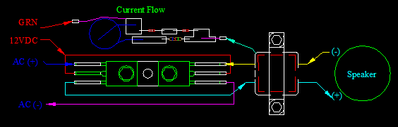
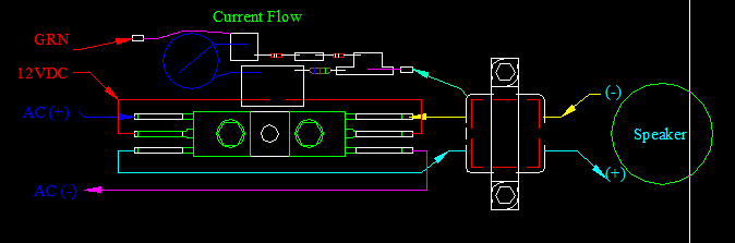
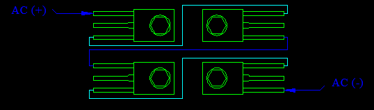
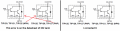
I left the ground out on purpose. That schematic is not the one I have and it's not wired that way. you would have to use a dual coil speaker which are only $45.00 but don't want to do that. I've been checking around for center tapped speakers cos the originals only had three connections. one on either side of the "-0 VAC" Radio speaker (-) or how ever you want to say it, to do the push-pull. It's missing the output transformer. The ground section that mine has, that one don't. It can use any two wire speaker. I know there are two different voltages on it (we discuss that). if you follow the wires and PCB connections through circuitry my schematic is right " if you hook the 12VDC to the bases which is what I asked".AG said:The schematic in the patent is correct, why don't you use it?
I've also read:
I'm trying to copy the one "I" have.poster said:I owned a pair of Tenna Mind Blowers. I dissected one of my Tenna Mind Blower amplifiers to find out why I was measuring 25 Volts RMS across the speaker terminals with a Fluke 8060A True RMS DMM from a 12 Volt DC source. That calculated out to about 78 Watts RMS at 8 ohms with them cranked way up. They had a standard 8 ohm single voice coil speaker. The speaker leads were connected at points 45c and 46c in the posted schematic drawing. The center tapped winding that you see in the output section of the drawing is the output transformer and not the speaker VC as some have concluded here. They do not show the speaker being connected to it in the schematic.
Edit: And I did read the patent where it said 45C and 46C were the voice coil. I wanted you to read where it hooked up to a two wire speaker.
Last edited: