Just some general questions about remaking something from the past

Status
Not open for further replies.

Thread Starter

Berzerker

Joined Jul 29, 2018
623
I'll try it again. That was wrong I hadn't had my coffee yet and it was early.
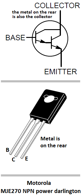
"IF" this is a correct pin layout of a Darlington NPN transistor:
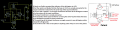
Image #1

And this is a schematic of a Darlington NPN transistor:
Image #2

And now I'm just assuming that (C) stands for collector (B) stands for base and (E) stands for emitter. According to image # 1: (B) is an outer pin "meaning not the center one". (C) is the center pin (E) is the other outer pin (yes)?.
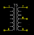
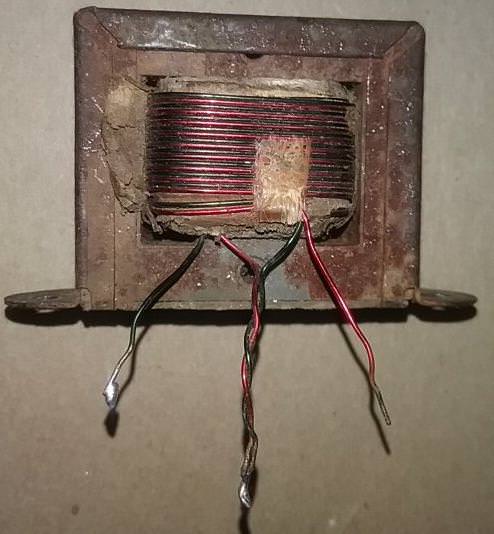
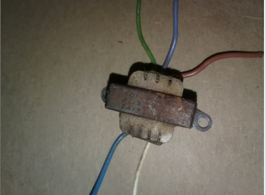
Correct me if any of this is wrong. Now if all above is correct then the 12VDC connects to the "collector" or center pins and only to the center pins on BOTH transistors. Again correct me if I'm wrong but there are "two" different voltages coming into it VAC for speaker inputs and VDC to power the transistors (YES)?. I know you can't just hook them together. Now if image #1 is correct and (B) stand for base then the speaker input (+) goes to one base of one of the transistors and the speaker (-) goes on the base to the other transistor. I can't change what they are connected too. I posted a pic of the actual transformer showing it only has four (4) wires. And I know this is how a center tapped transformer looks now:
There are "not" five wires no matter what the Tenna schematic says. There are "no" input wires on it at all. they connect as I said in post # 192. Pic of actual Transformer again;
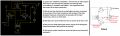
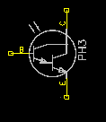
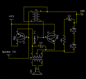
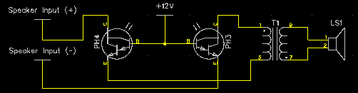
Please tell me where the center tap is on it, or the input wires? Unless the schematic you got is from the very first ones and that is not what I have. I have updated my Diptrace schematics again and here's how it looks:

This all based off image # 1
Edit: only two verification errors and their on ground on T2
Edit 2: Verification "NO" errors found. had wires not connected but looked like it.
 
Last edited:

shortbus

Joined Sep 30, 2009
10,049
"IF" this is a correct pin layout of a Darlington NPN transistor:
The "if" will get you every time. Never go by a generic or other brand data sheet when working with transistors, Darlington or not. The to my knowledge is no convention to how the pins are numbered, it is kind of up to who makes them. So ALWAYS get the data sheet for the brand you are using. I'm sure I'll be told what was just said is wrong, but not in my experience.

And I know this is how a center tapped transformer looks now: There are "not" five wires no matter what the Tenna schematic says.
I'm wondering if this is a 'transformer' at all. It could be a mutually coupled inductor.
Mutually_inducting_inductors.PNG From, https://en.wikipedia.org/wiki/Inductance
 

Thread Starter

Berzerker

Joined Jul 29, 2018
623
Thanks shortbus. I'm still not sure what it is either. I know it's not a center tapped transformer. I found a place in Birmingham, Al. that will test them both "Input and output transformers or not" for me but I will have ship it there and wait for the results. There is another transformer on it but it goes to the speaker out and it does have five wires.

The top wires all come from the board. The brown goes to ground as in my schematic above. the bottom two go to the speaker itself.
Found this on another website
website said:
Tenna "mindblowers" were such an example. The pnp pushed one coil and the npn pull the other coil, all on the same bobbin.
I meant to ask I know verification in diptrace is not like putting one together and it works kinda deal. will it simulate power on the board and components to see if anything "blows" up? and about quote above the pin layouts would be the same just the transistors would operate reverse from one another right?
 
Last edited:

Audioguru

Joined Dec 20, 2007
11,248
I am glad that now you understand the pins on some old darlington transistors. But the pins on European and Oriental transistors are different.

It seems that your transformer is different to the schematic on the patent.
You found a completely different MindBlower description on another website that has a PNP Darlington and an NPN Darlington on two separate coils on the transformer. Maybe your speaker is like that. A simple continuity and transistor test with a multimeter will prove it.
Some Mindblower speakers had custom made 3-wires speakers and others had a center-tapped output transformer driving a normal 2-wires speaker.

Who knows which version you have?
Your schematic is still completely wrong.
 

Thread Starter

Berzerker

Joined Jul 29, 2018
623
Please AG and Members don't take this as me ranting. I just want to post some facts:
To AG:
I wouldn't doubt my schematic is wrong AG. But every time I tell you what I do have you tell me "no it's not". I tell you the 12VDC goes to the center pins on the transistor and you say it don't. I have two of them, one assembled one disassembled. Two PCB boards, two of everything and I'm telling you the 12VDC goes to the center pins alone. No matter if it's (E), (C) or (B) on (X) transistor. A PCB board has copper wires that you can see running through it so I "CAN" see what goes to what. I've posted pictures of the actual Mindblower on here and you still tell me it's wrong. you say it's a center tapped transformer? I posted a pic and it has no input wires, still I'm wrong. I posted a pic with numbers on it showing you how the input and ground wires attach to it and still I'm wrong. I say the transformer or what ever it is connects to the ground with the twisted wires in the middle and the other two ends go to the speaker inputs on each of the transistors, you say it don't. I'm looking right at it. The schematic you post doesn't even have a ground section to it? I post it has two capacitors and you say "the schematic shows no capacitors" again I'm looking right at them and even pointed it out in a pic cos there are two. The schematic you post I have seen on several websites and have never seen it on an actual document with "Tenna Mindblower patent stamped on it". If you go to this page which you showed me: https://www.trademarkia.com/mindblower-73067650.html
and scroll down it says:
above website said:
Design Search: (NO DATA)
This could be just someone who jotted down a rough sketch and it wasn't from the tenna corp. You said my schematic was wrong? If using the Motorola MJE270 transistor then it "is" correct or that wasn't what was used at all. What's on the PCB board and wires that are attached as it is posted are correct. If it's wrong I didn't design it I just posted how the wires and components hook together. So I'm guessing it's not a MJE270. The reason I attached the wires as shown on my last schematic I used the MJE270 and if the collector is in the middle then that transistor diagram is of some other transistor not the MJE270. So you would attach the 12VDC to the collector. Haven't found a transistor diagram with (C) marked where the (B) is on that one (yet).
 
Last edited:

shortbus

Joined Sep 30, 2009
10,049
Here is the patent of the MindBlower speaker with the schematic I have been using:
https://patents.google.com/patent/US4130725A/en

The schematic you posted yesterday has many errors that I describe on my attachment:
AG, I have found in my looking at patents and trying to match them to circuits and even machines they don't often match what is actually done. The patents are often misleading to keep others from directly copying, they are only meant as a reference to get a patent.
 

Thread Starter

Berzerker

Joined Jul 29, 2018
623
AG and shortbus said:
Yea the first pair or even maybe the second pair I had, had this speaker configuration. The later ones added the transformer in post #206 to eliminate using the dual coil speaker. They were no good and often couldn't take the wattage and would blow. So my work around was to buy two sets of two wire single coil speakers and wire them in series "four speakers in my trunk". Two I usually mounted to my backseat metal braces that are in car trunks and the other normally.
shortbus said:
With this being an amplified crossover network, I think my mutually coupled inductor is more likely.
I am still reading on this shortbus. I'm also doubting it's a transformer too. Why would you ground a transformer if it connected as it is? It would short something out????
AG said:
your C3 and C4 are in the wrong place and aren't on the patent
from post #209.
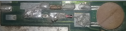
This is C3 in my schematic.

again "no their not". This is what your patent is missing. I had removed a diode and thought to take some pics before I went any further.
the other you mentioned C4 here's the answer to it.
http://www.pcbheaven.com/wikipages/Transistor_theory/?p=6
website said:
Coupling and Bypassing Capacitors

As we said before, transistors are DC components. This means that the output will also be a DC voltage. But if we amplify an AC voltage, then we probably want to get an AC voltage at the output as well. How is this done? Simple, with a coupling capacitor. A capacitor operates as a resistor in AC and as an open circuit in DC. It is not the purpose of this theory to analyze in details the capacitor's behavior in AC and DC. Nevertheless, it is important to have some very basic knowledge about capacitors.
shortbus said:
Berzerker, You are correct on your pin numbering on the Darlintons.
I'm not so sure on that shortbus (?) I'm still learning.
 
Last edited:

Audioguru

Joined Dec 20, 2007
11,248
With this being an amplified crossover network, I think my mutually coupled inductor is more likely.
The very simple amplifier does not have a crossover network in it.
The crossover is probably simply a capacitor in series with the tweeter to block low frequencies from blowing up the tweeter.
Somebody said there was a switch that cut the highs (disconnected the tweeter?).
 

Audioguru

Joined Dec 20, 2007
11,248
So my work around was to buy two sets of two wire single coil speakers and wire them in series "four speakers in my trunk".
Where the two speakers are connected together then you will use that connection as the center-tap connected to 0V (ground). Then the total output power will be very low and maybe with severe distortion because the center-tapped transformer or center-tapped voice coil in a single speaker has each half magnetically coupled together. The magnetic fields in the voice coils in two separate speakers are not coupled together. When one Darlington pulls its end of the center-tapped coil positive then the magnetic coupling pushes the other end negative so the entire speaker gets doubled the voltage AC. Your idea has one speaker being pulled positive by its Darlington but the other speaker does nothing until its darlington pulls it positive when the other speaker does nothing. Each speaker gets averaged DC which is bad instead of AC.

Two I usually mounted to my backseat metal braces that are in car trunks and the other normally.
For a speaker to sound properly then it must have an enclosure designed for its detailed spec's.

This is C3 in my schematic.
The photo does not show where it is on the schematic.

the other you mentioned C4 here's the answer to it.
http://www.pcbheaven.com/wikipages/Transistor_theory/?p=6
Your link shows coupling capacitors. You show C4 shorting the high frequencies between the emitters.
 

Thread Starter

Berzerker

Joined Jul 29, 2018
623
AG said:
Your link shows coupling capacitors. You show C4 shorting the high frequencies between the emitters.
Why are you always doubting me? I've been at this now for only 21 days (three weeks). And I would like to think I've done OK at for such a short time. I think your just trying to pluck me for information cos you want to build one yourself... :):rolleyes::rolleyes::D. Just kidding AG.
But just incase your taking notes I'll play along:

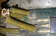
The green and blue wires you see (left) go into the output transformer and the capacitor "IS" across the emitters. The top connection is coming from the other transistor and it is also the emitter side. Did you read the article I posted? Now I'm not sure but it said something about it pulling the DC off the emitters. Again I'm new at it so I'm still "researching" Oops I mean reading about it. You might want to start giving me a little credit instead of doubting me all the time.
Edit: I don't think this is a push-pull type configuration because the emitters are not connected together as in most articles I've read, Unless it is done in the output transformer "now there's a thought".
 
Last edited:

Audioguru

Joined Dec 20, 2007
11,248
C4 looks like a low value ceramic capacitor that might be used to smooth a high frequency peak from the transformer so it shorts the peak frequency.

A normal push-pull amplifier has no output transformer. It has a transistor pulling one wire of a speaker positively and another transistor pushing that speaker wire negatively. The other speaker wire is connected to 0V (ground) or to the output of a second amplifier with opposite phase making a bridged amplifier that produces almost double the voltage and current swings for almost 4 times the power.

The Mindblower push-pull uses a center-tapped voice coil or center-tapped output transformer so that each transistor pulls positively one-at-a-time but the center-tapped transformer operates like a see-saw where when one end drives up (positively) then the other end goes down (negatively) even though the turned off darlington transistor does not drive negatively. The transistor going negatively is turned off but the transformer action drives that end of the transformer winding with power. The center-tapped transformer action produces the opposite phase.
 

Thread Starter

Berzerker

Joined Jul 29, 2018
623
Thank you AG. I am talking to some people over the phone that "might" have some information for me. It's the old let me put you in touch with so and so they should know. Old timers that were actually there during the tube era. Of course I've also heard the same thing you've been saying they probably don't make it anymore. But it never hurts to find out.
 

Thread Starter

Berzerker

Joined Jul 29, 2018
623
I already know AG your going to say "Wrong". But I'm only asking about current flow. I been testing the components with a meter (again) and I know we've figured out they are NPN transistors. Also been looking at pin configuration on both NPN and PNP most of the morning again. Reading about the difference in how they work and the current flow through them. Read below before you tell me how bad my schematic is "OK".

Start with 12VDC it energizes the bases and activates the transistor right? Speaker input (+) comes from the radio and is positive current right?
It also goes into the collector (PH4) through the transistor and out the emitter right? Goes in the output transformer, comes out and goes to
speaker (+), through the speaker itself and out speaker (-) right? Back into the transformer and into the collector on PH3 and out the emitter to radio speaker negative right? Don't you have to have more current going in the collector on the transistor than the base? With two different currents on it wouldn't their be VDC going into your speaker also? I'm trying to figure out how the DC was remove or rather not allow to go through the speaker. I guess you could call it bleed through. Transistors are DC current based (normally) right?
 

Audioguru

Joined Dec 20, 2007
11,248
Absolutely NOT! Your new schematic and text are absolutely wrong and mixed up. Since your circuit shows nothing connected to 0V then the transistors do nothing and no current will flow.

The "speaker" inputs from the radio are not positive and negative DC. Since the radio outputs might be 0V, +12V or any voltage in between then the input transformer blocks their DC but passes their AC signal. The center-tapped secondary of the input transformer does not have a positive current and a negative current, Instead it has inputs with a positive phase and a negative phase. The phases are AC with opposite phase. One has + AC phase and the other has - AC phase.The bases are for the AC signal inputs and a low DC bias voltage. The collectors of these NPN emitter followers are +12V and the emitters feed the ends of the center-tapped speaker or center-tapped output transformer. The center-tap is connected to 0V so that positive-going AC to a transistor base causes the transistor to conduct and feed some of the +12V current into the center-tapped special speaker or center-tapped output transformer.

A Darlington transistor has a minimum current gain of 1000 which means that 1mA into the base results in at least 1000mA at the collector or emitter.

No DC current flows in the center-tapped 3-wire custom speaker because both emitter outputs have the same DC voltage of about 0V. When there is an AC signal then when one base and emitter drive positively then center-tapped transformer action drives the other base and emitter negatively (opposite phases).

The schematic in the patent is correct, why don't you use it?
 
Status
Not open for further replies.
Top