Just some general questions about remaking something from the past

Status
Not open for further replies.

Thread Starter

Berzerker

Joined Jul 29, 2018
623
One of the transformers is a "Isolation transformer" Their designed to block VDC current from entering the VAC side.
Still working on the main Transformer.
Edit: Shortbus I value your information and "Appreciate you helping me out"
I will try that. I have found several capacitors only with a higher voltage but, with the right (pf) or (uf).
Edit 2: Some you have to buy 500 some 2500. I don't need that many to test with. if I use the higher voltages I can order one.
And it's just a guess at this moment on the Isolation transformer but everything VAC and VDC grounds through the VDC side.
 
Last edited:

Thread Starter

Berzerker

Joined Jul 29, 2018
623
Here is a vid on what I think is going on:
Here he talks about capacitive coupling which I think is what I have.
OopS I didn't mean to link the videos. I only wanted the link to it.
 

shortbus

Joined Sep 30, 2009
10,049
Some you have to buy 500 some 2500. I don't need that many to test with. if I use the higher voltages I can order one.
The higher voltage won't hurt a thing. So pick one they have in stock. The ones that require 1000 or more they don't carry because of not much demand, so they have to order a whole reel to sell to you.
 

Thread Starter

Berzerker

Joined Jul 29, 2018
623
Put an request into Triad Magnetics. Maybe someone that's been doing transformers for years can tell me what they are???
haven't heard back "yet".
If I have to I'll pay to ship them there and let them test them and see if there's something to match, replace.
 

Audioguru

Joined Dec 20, 2007
11,248
Put an request into Triad Magnetics. Maybe someone that's been doing transformers for years can tell me what they are???
The custom-made input transformer is not used today and was only used in the old MindBlower speaker. Your input transformer has many spec's that must be calculated and priced (a telephone quality transformer is cheap, a hifi transformer is expensive). The spec's include how much voltage boost, power and input and output impedances. If the input transformer you have is not damaged (it looks rusted) them maybe a transformer manufacturer can test its spec's then copy it.
 

Thread Starter

Berzerker

Joined Jul 29, 2018
623
AG said:
Your input transformer has many spec's that must be calculated and priced (a telephone quality transformer is cheap, a hifi transformer is expensive).
Never hurts to find out.
AG said:
If the input transformer you have is not damaged (it looks rusted) them maybe a transformer manufacturer can test its spec's then copy it.
They still make isolation transformers. I just need to know the ratio.
And I'm still checking but I think this is the output transformer just the wrong ratio:
https://www.fullcompass.com/prod/15...mi57yo8u_s3aivu5ubch1gzwv5eaeyasadegiwt_d_bwe
And it needs to be a foot mount.
Edit: and I forgot to add it might be a line matching transformer.
 
Last edited:

Audioguru

Joined Dec 20, 2007
11,248
I think the patent for the antique speaker says the ratio for the input transformer (1:4?).
You found a microphone transformer that operates at a level and power that are way too low and its primary is not center-tapped. How can it drive a low impedance speaker with many Watts?
You need custom made transformers because nobody uses transformers anymore for speakers.
 

Thread Starter

Berzerker

Joined Jul 29, 2018
623
someone from 4 years ago said:
In an output voltage test I did on one channel with the speaker connected, and measured with a true RMS Fluke DVM, I had a reading of up to 25 volts AC across the output, which is 78.125 Watts RMS. For a wattage rating of 30 Watts True RMS per channel, Tenna was being very conservative in their output rating.
They were wanting to do the same thing I am.
Don't be so negative AG. Maybe I won't find that transformer (?). But I still might find something or somethings that will do the same job.
 

shortbus

Joined Sep 30, 2009
10,049
How can it drive a low impedance speaker with many Watts?
Are you sure about the values on the speakers that were from that era? I remember many of them being marked 6 ohm, and some being marked 8 ohm, back then. I know they are usually ~4 ohm today, but back when the Mindblower was being used?
 

Thread Starter

Berzerker

Joined Jul 29, 2018
623
I know AG is probably right that they don't make that particular transformer anymore. But if you look on Digikey there are hundreds.
https://www.digikey.com/products/en/transformers/audio-transformers/162?k=transformers
Maybe I will have use two or even three to do the same job. again I don't know (yet). 4 ohm speakers can handle more watts "yes"?.
I have found that the transformer winding is 72 turns but not the ratio. AG said 1:4 "I'm still checking this out" What gets me after looking closer at how it's connected on the board baffles me. you have 1 to 5 volts AC "guessing here" coming in on the transformer while it is also connected to the DC ground. It is two wires (red and black) wound around the core with each ends exposed, i.e. 4 wires. Why would you put AC on the collector with it grounded to the DC side?
Edit: here are some line input transformers
https://www.lundahltransformers.com/line-input/
they do still make them but this one (IS) expensive. They have to make the same thing somewhere else cheaper:
https://www.markertek.com/product/jt-11-bmcf/jensen-jt-11-bmcf-line-output-audio-transformer
 
Last edited:

Audioguru

Joined Dec 20, 2007
11,248
Transformers are used on speakers in the ceiling of stores. They are rated for 1/4W to 1W which is not enough. Their primary is designed for 70V that a car radio does not produce. Also they are not center-tapped.

A 4 ohm speaker produces double the power of an 8 ohm speaker when they are both fed a certain voltage. 8 ohm speaker are used in homes because a higher supply voltage comes from an electricity supplied power supply and 4 ohm speakers are used in cars due to the low 12V available.

Transformers work only with AC, never with DC. The input transformer is fed AC from the car radio and if both wires have the same DC then the transformer does not have any DC current in it. An old car radio produced full power of about 4W into 4 ohms which is 4V RMS which is 11.3V p-p. The input transformer of the Mindblower speaker might double the AC voltage. The Darlington transistors in the Mindblower speaker are emitter-followers that have no voltage gain and the special center-tapped or newer output transformer might increase the AC a little more.

The input transformer is not connected to ground on the patent schematic and the center-tap of the speaker or a newer output transformer is shown connected to ground. Look on Google to see how the ends of a transformer's center-tapped winding swing positive and negative in reverse of each other.

Again, a transformer does not use DC and also has no "collector".

Line level transformers use and produce much less current than a speaker uses. Output transformers for tubes are useless for your old speaker unless you use tubes and a high voltage power supply.
 

Thread Starter

Berzerker

Joined Jul 29, 2018
623
Now I'm not trying to argue or say your wrong AG but...….

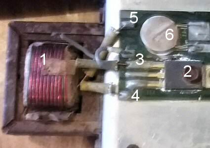
1. Is the transformer in question.
2. The NPN transistor
3. Speaker input plus (+) on collector
4. Speaker input minus (-) on second transistor collector
5. chassis ground for 12VDC.
6. One of the capacitors your schematic does not show.
Edit: If you look at the top of the number (3) and the little wire that connects to nothing is the 12VDC (+). It connects to both transistor bases.
Edit 2: This is the one I dismantled to test the parts. The other still has the wires connected to it, So I know which one is what and I did have 5 pairs or so. And (5) has GRN stamped right beside it on the PCB.
Edit 3: Now I think about it more and you all know I'm no electronics expert but this might be the isolation transformer to pull the VDC off the transistors from it being applied to the bases of the transistors and the other is the power transformer. I might have it backwards.
 
Last edited:

Audioguru

Joined Dec 20, 2007
11,248
No.
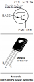
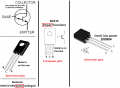
I showed before the datasheet of an old Darlington transistor that showed the middle pin is the collector that connects to +12V.
Like on the patent schematic your number 3 is the base (input of the Darlington transistor) connected to the input transformer.
Your number 4 goes to the base of the second Darlington transistor.
The schematic in the patent shows no Ground on any pin of the input transformer.

The transformer with a center-tap boosts the AC signal voltage, isolates DC voltages of the car radio from the bases of the darlingtons and produces the opposite polarity AC signals to feed the Darlington transistors.
 

Attachments

Thread Starter

Berzerker

Joined Jul 29, 2018
623
Now that makes sense AG. If you look at a NPN transistor you get a different pin layout. I'll go back and look at the difference in a Darlington and a regular NPN. It had me confused. and I thought the base was the one you put volts to.
AG said:
The schematic in the patent shows no Ground on any pin of the input transformer.
Pic shows different. I have changed nothing on the pic I posted. Just removed wires to disassemble.
There are two sides to it and it has to be grounded somewhere, somehow. you can not just put volts "anything" to something without a ground.
Now does the speaker input (+) and (-) go to the base or the collector? If it goes to the base then it's the middle pin???/ I got one I'm looking at. From all my reading the collector, collects what the emitter is going to put out. Base is for voltage.
 

Thread Starter

Berzerker

Joined Jul 29, 2018
623
t

Now if I have collector and base mixed up then I'm a fault. But here's how it goes.
But only place a transformer between the emitters and speaker.
 

Thread Starter

Berzerker

Joined Jul 29, 2018
623

Here is it all.
I think you are forgetting there are two different voltages AG. The DC has to hook up somewhere and the AC has to hook up somewhere. 12VDC on the base to activate the transistor. and speaker input to go through the collectors and out the emitters on the transistors.
 
Last edited:

Audioguru

Joined Dec 20, 2007
11,248
You are still looking at the pins of a little low power transistor. The collector on a larger power transistor gets hot so the collector is the metal tab and is also the middle pin.

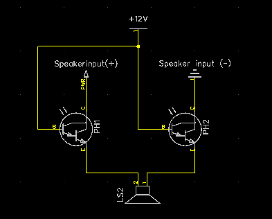
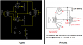
Your circuit is completely wrong and will do nothing. It has no center tap on the transformers so that the Darlington transistors can swing oppositely.
The base is supposed to be biased at about +1.4V because the two base-emitter voltage drops in a Darlington are also about +1.4V then the emitter output is 0V with no AC signal.

The center-tap on the transformers allow the AC signals on the Darlington transistor bases and emitters to work oppositely so that when one transistor goes positive then the other transistor goes negative.
 

Attachments

Alec_t

Joined Sep 17, 2013
15,149
You have the two ends of the top transformer winding shorted together.
The collector of the right-hand transistor is shown grounded.
 

Thread Starter

Berzerker

Joined Jul 29, 2018
623
Thanks Alec_t, AG and MrChips . OK the pin configuration in my head is wrong but it still doesn't negate the fact that one of those pins on the transistor is going to ground. Even with the pin input points moved around (post #198 by AG) it only shows that the base is now attached to ground. I have a pair (two) of these and I only disassembled one. I might should have noted that I'm not good in Diptrace yet and have things turned or hooked up wrong. Pic in post #192 does show those middle two wires on the transformer going to ground cos it is marked on the PCB board and there is a black wire coming off the one I still have intact that you hook to GRN (chassis). There is a red wire coming off the PCB with PWR stamped right beside it and using AG's pin layout is now connected to both collectors on the transistors ONLY. There are a light blue and white wire attached to one of each of the bases "using AG's pin layout" for speaker input. At the other end "the second transformer bottom" that hooks to the speaker itself are a blue and white wire to correspond with the top to show (+) and (-) and which wire goes to which.
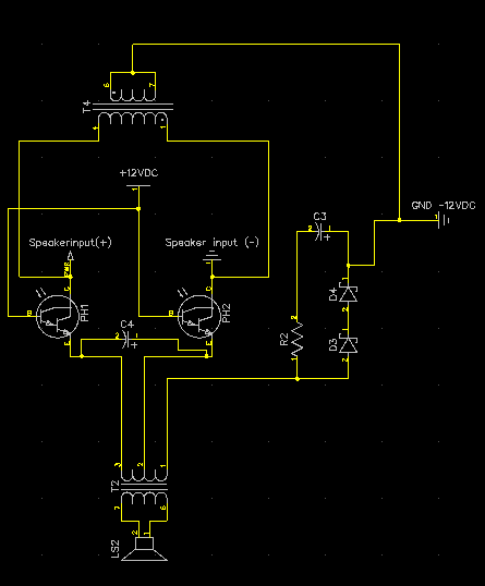
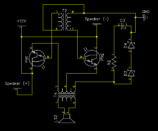
I have updated my schematic using AG's pin layout:

But still something is wrong with what y'all tell me. Pic in post #192 noting that (5) is GRN and is on the Amplifier board (the top transformer). "assuming" that the dots on pins #1 and #7 are the same wire and pins #5 and #9 are also, just ins and outs of each. Then the schematic above is wrong?
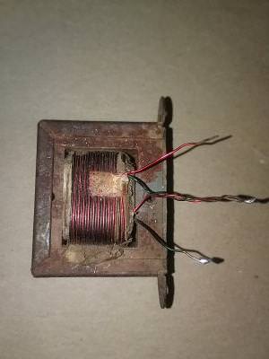
Pic of transformer off:

Notice that there are a red and black wire twisted together in the middle they go to GRN. The other two again red and black hook to each base of the transistors. The only thing missing is the capacitor across both emitters as in post #196.
Note to AG: Just assume "pretend" the top transformer is center tapped and is 4 wire. I'm not good in Diptrace and don't know which transformers are what yet. If I knew I would place one in the schematic.
 
Last edited:
Status
Not open for further replies.
Top