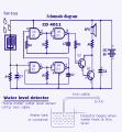
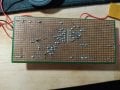
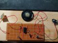
I got this new schematic and I've tried to construct it on the stripboard

Status
Not open for further replies.

Thread Starter

Hannan007_

Joined Oct 31, 2021
44
Because you connected your sensor directly from positive 9V to GND, you are shorting the battery when you wet the sensor.

So your battery must be very week by now and need to replace with a new one. Check the 2 things what Mr Chips said that you should take care of.
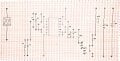
FYI this I'm using the new battery yesterday cause when I measured the voltage on the old batteries it is quite low. If my batteries is shorted it will be hot right?
 

Thread Starter

Hannan007_

Joined Oct 31, 2021
44
This the battery voltage and it should be 9V.
Disconnect the speaker and check this voltage again. If it is still low then you need a new battery.
Leave the speaker disconnected and when you do get 9V repeat the other voltage measurements.
I've fixed my circuit based on what Mr.Chips said on the #78 comments. The reading on each pins now are relevant

P1 = 0.04 (constant value)
P2 = 2.65 (constant value)
P3 = 5.36 (constant value)
P4 = 5.36 (constant value)
P5 = 5.36 (constant value)
P6 = 5.35 (constant value)
P8 = 4.42 (constant value)
P9 = 4.47 (constant value)
P10 = 3.91 (constant value)
P11 = 4.41 (constant value)
P12 = 5.33 (constant value)
P13 = 3.33 (constant value)
P14 = 8.45 (constant value)
*please take note that the speaker are CONNECTED to the circuit while measuring the voltage on each pin of the IC1 and the circuit worked well. I will post my new fixed layout on this thread later. The speaker give a beep beep sound when there are water on the circuit but the sounds are quite slow but you can hear it clearly if u are close enough to the circuit.
 

absf

Joined Dec 29, 2010
1,968
Well done!:)
Make sure on the ROW between P8 node and the R6/spk node is cut or else it won't work.
Some members here may come out with ideas on how to make the speaker sound louder with/without modifying the circuit.
 

LesJones

Joined Jan 8, 2017
4,524
In the layout drawing in post #83 you have the link from the bottom end of the sensor connected to P2. It should be connected to pin 1. I spotted that while trying to understand the voltage reading (2.65 volts.) on pin 2. (I would have expected it to be close to 9 volts when the sensor input (Pin 1) was close to zero volts.)

Les.
 

Thread Starter

Hannan007_

Joined Oct 31, 2021
44
Well done!:)
Make sure on the ROW between P8 node and the R6/spk node is cut or else it won't work.
Some members here may come out with ideas on how to make the speaker sound louder with/without modifying the circuit.
yup I've cut the track after I've learn them
 

Thread Starter

Hannan007_

Joined Oct 31, 2021
44
In the layout drawing in post #83 you have the link from the bottom end of the sensor connected to P2. It should be connected to pin 1. I spotted that while trying to understand the voltage reading (2.65 volts.) on pin 2. (I would have expected it to be close to 9 volts when the sensor input (Pin 1) was close to zero volts.)

Les.
I'm sorry my mistakes on that drawings, but the sensor actually connected to P1 there was a mistake on that drawing
I think that's why the speaker is not loud because of low voltage? This is my theory. The only pin that are close to 9V is PIN 14 which 8.45
 

Alec_t

Joined Sep 17, 2013
15,149
I think that's why the speaker is not loud because of low voltage?
Yes. When the speaker draws current the battery load is about 18 Ohms. It's asking a lot of a poor little 9V battery to provide 9V/18Ω = 500mA. The battery's internal resistance probably drops the speaker voltage way down. A beefier supply would be better.
 

MisterBill2

Joined Jan 23, 2018
28,055
To check the assembly closer to actual conditions you can use wet fingers across the sensor. A real water connection will not be a short circuit.
And to reduce the battery drain while sounding you can increase R6 from ten ohms to 100 ohms and add a capacitor across it, (in parallel) , some value at least 0.1mFd, or more. That will also make the sound a bit different.
 

MrChips

Joined Oct 2, 2009
35,030
Dry the water sensor completely.

Take the voltage measurements at IC1 pins with respect to -ve rail.
Also show the voltages at ECB of both transistors Q1 and Q2 with respect to -ve rail.
 

Thread Starter

Hannan007_

Joined Oct 31, 2021
44
I think I can close this thread as my circuit is now worked perfectly this the video of my circuit

Thank you to all fellow engineers, electrician and everyone who helped me doing this circuit. It is a pleasure to be thought by you guys as I learn something new which I've never learned in classes. I would like to thank you to @MrChips @absf @dl324 @LesJones @BobTPH @MisterBill2 who always give ideas to solve the problems. As a total beginner I'm very impressed how a small circuit have lots of information that most of them I didn't know. I will ask questions again if I have problems that I couldn't answer through this website. I will have finals next week, wish me luck. Thanks again to all of you.
 

MrChips

Joined Oct 2, 2009
35,030
Wait! You're not done yet.

When you get a chance, do the measurements I posted in #92.
Then tell us what changes you made to get the speaker working at proper volume level.

Good luck on your exams!
 

Thread Starter

Hannan007_

Joined Oct 31, 2021
44
Wait! You're not done yet.

When you get a chance, do the measurements I posted in #92.
Then tell us what changes you made to get the speaker working at proper volume level.

Good luck on your exams!
ouhhhh sorry I didn't see ur comments I got 0.01V on PIN #1

*red probe connected to transistor and black probe connected to -ve rail
Q1
B = 0.00
C = 8.97 (constant value)
E = 0.54 (constant value)

Q2
B = 0.54 (constant value)
C = 8.68 (constant value)
E = 0.00

I didn't make any changes since I post #88 of my breadboard at first it gave me slow sound but later that night when I connect it to the batteries and I put water on the sensor it gave my the sound on #93 video and I was like "ooook" but it is a great news for me. And thank you for your wish I really appreciate the hard work u put to help me thanks a lot.
 

Thread Starter

Hannan007_

Joined Oct 31, 2021
44
To check the assembly closer to actual conditions you can use wet fingers across the sensor. A real water connection will not be a short circuit.
And to reduce the battery drain while sounding you can increase R6 from ten ohms to 100 ohms and add a capacitor across it, (in parallel) , some value at least 0.1mFd, or more. That will also make the sound a bit different.
that sound interesting, but I think I will not modify anymore cause the sound from the speaker is so much better now but thanks for the info. The capacitor will double the voltage right? The only thing I know what resistor does is to store energy cause I'm still in my diploma hahaha but that is a good information you shared
 

BobaMosfet

Joined Jul 1, 2009
2,211
Hi im a student and a beginner, so I got this new schematic and I've tried to construct it on the stripboard but it didnt work

I have de-solder the component on the stripboard and trying to make a new one

this is the scehamatic

any help would be appreciated
@Hannan007 A couple of things- I suggest using breadboard while learning, no solder involved, and secondly, having a schematic isn't enough- You need to be able to tell if the schematic is any good- this (believe it or not) is what got me into learning electronics a long time ago. I saw schematics, and I found they were usually wrong. And I decided to learn electronics so _I_ could verify whether or not a schematic was any good or how I could fix it, before trying to build it.

I recommend this book:

Title: Understanding Basic Electronics, 1st Ed.
Publisher: The American Radio Relay League
ISBN: 0-87259-398-3
 

Thread Starter

Hannan007_

Joined Oct 31, 2021
44
@Hannan007 A couple of things- I suggest using breadboard while learning, no solder involved, and secondly, having a schematic isn't enough- You need to be able to tell if the schematic is any good- this (believe it or not) is what got me into learning electronics a long time ago. I saw schematics, and I found they were usually wrong. And I decided to learn electronics so _I_ could verify whether or not a schematic was any good or how I could fix it, before trying to build it.

I recommend this book:

Title: Understanding Basic Electronics, 1st Ed.
Publisher: The American Radio Relay League
ISBN: 0-87259-398-3
thanks for the information, I'm still trying to learn and understand the schematic, as you can see from this thread I still can't read schematic properly but as discussion were made it make me to easily understand the connection on the schematic. I'm still not very good at analysing the circuit like what does this component do to the circuit , what that component do to the circuit and so on. But like I said as discussion were made in this thread it gave me new knowledge that I've never learn in class. Before I made this thread I wasn't able to understand the connection on the IC on the schematic capture. What does the gate means etc. But now I'm able to understand the connection on the schematic. Maybe soon I will be able to analyse the circuit just like you were saying thus, will make a better circuit than the schematic. On the next semester I will have Arduino that is much more complicated than this circuit. Wish me luck and Thanks for the books suggestion.
 
Status
Not open for further replies.
Top