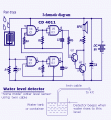
I got this new schematic and I've tried to construct it on the stripboard

Status
Not open for further replies.

MisterBill2

Joined Jan 23, 2018
28,050
I've tested it out , I got no reading on the first test with the meter on 2k and 20k rage it shows 0. The second test, which is negative terminal of the batt connector and pin 14. I got 0.21 with 2k range. Does it means my battery connector is reversed?
YES, it seems that there had been a reversal.
And please return here because there is a lot of wisdom available from some of the participants. And you will see that there are also a lot of folks just getting started. In addition, the disproving of concepts for greater than 100% efficiency is always interesting.
 

BobTPH

Joined Jun 5, 2013
11,618
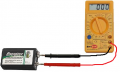
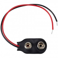
I've checked the polarity using the multimeter, it shows that the black wire is positive (+) and red is negative (-)
I would just like to point out that you are misinterpreting the reading on your meter.

You show a positive reading on the meter with the black probe in the black wire and the red probe on the red wire, then say that means the black wire is positive. No. That is backwards. When the meter shows a positive voltage, the red probe is the positive one. When it shows a negative voltage, the probe wire is the negative.

Bob
 

Thread Starter

Hannan007_

Joined Oct 31, 2021
44
Update:

I found a connectivity error which my jumper didnt connect to pin 1 of the IC. I connect my battery with the battery connector, the black wire to the positive pole of my battery and red wire to the negative pole of my battery. The speaker start to make a buzz noise even there is no water on the sensor board. So I have a question, is this a good sign or not
 

Thread Starter

Hannan007_

Joined Oct 31, 2021
44
YES, it seems that there had been a reversal.
And please return here because there is a lot of wisdom available from some of the participants. And you will see that there are also a lot of folks just getting started. In addition, the disproving of concepts for greater than 100% efficiency is always interesting.
can it be fixed by replacing a new battery connector?
 

MrChips

Joined Oct 2, 2009
35,029
Test your battery, contacts, and cabling.

Remove the battery and test it directly with a voltmeter. Red lead goes to small button (+). Black lead goes to flanged clip (-). You should be reading close to 9VDC.


1635774279431.png


Unsolder the battery clip from your board.
Connect the battery clip to the battery and measure the voltage at the red (+) and black (-) wires of the clip.

1635774479922.png

Use your meter often to troubleshoot your circuit.

(1) Use the DMM in V DC mode to measure voltages at various points around the circuit. Keep the black lead on the -ve side (common) of your circuit.

(2) With the battery removed from the circuit, use the DMM in continuity test mode or 200Ω range to test for direct connections of points in the same node.

(3) With the battery removed from the circuit, use the DMM in low and high resistance ranges to look for shorts where there should be no short, i.e. look for 0Ω where expected and high resistance where expected.

(4) With the battery removed from the circuit, use the DMM in low and high resistance ranges to get an estimate of resistance values, knowing that a resistance measurement in-circuit will be influenced by all other components in the circuit.
 

Thread Starter

Hannan007_

Joined Oct 31, 2021
44
sorry for late update the circuit still doesnt work. I've checked the resistance each of the resistor and all of them are in good conditions but when I tried to test out voltage through them, it gave me no reading except resistor 1 R1. One more thing, the speaker which is 8 ohm 0.5 watts didn't sound well it gave me static noise and it is very quite I can barely hear it. I've try to test it out by making a circuit which connect LED and the speaker, the LED emits light very well but the speaker still gave me static noise. And what's the meaning by 8 ohms and 0.5 watts on the speaker, is it the minimum power or the max power?
 

AlbertHall

Joined Jun 4, 2014
12,640
With the sensor wet, connect the meter black lead to pin 7 of the IC, and then measure the voltage reading on the other pins and list them on here.
 

BobTPH

Joined Jun 5, 2013
11,618
Look at your post #39. You say:

“Black probe connected to black wire.” And your multimeter shows a positive voltage.

Then you say “Black probe connected to red wire.” And your multimeter shows a negative voltage.

Your conclusion is the the black wire is the positive.

Do you believe this is correct?

Bob
 

Thread Starter

Hannan007_

Joined Oct 31, 2021
44
Look at your post #39. You say:

“Black probe connected to black wire.” And your multimeter shows a positive voltage.

Then you say “Black probe connected to red wire.” And your multimeter shows a negative voltage.

Your conclusion is the the black wire is the positive.

Do you believe this is correct?

Bob
I forgot to update this issue. I've tested it out based on the what Mr. Chips said on the #67 comment. I found that my red wire on the connector is positive and black wire is negative, then I've connected it to the circuit but the circuit still doesn't work.
 

Thread Starter

Hannan007_

Joined Oct 31, 2021
44
With the sensor wet, connect the meter black lead to pin 7 of the IC, and then measure the voltage reading on the other pins and list them on here.

P1 = -0.02
P2 = 1.67 (value keep is declining)
P3 = 4.80 (value keep is declining)
P4 = 0.00
P5 = 4.89 (value keep is declining)
P6 = 4.87 (value keep is declining)
P8 = 4.84 (value keep is declining)
P9 = 4.83 (value keep is declining)
P10 = 0.00
P11 = 4.86 (value keep is declining)
P12 = 0.00
P13 = 1.39 (value keep is declining)
P14 = 4.89 (value keep is declining)

I connected black probe to Pin #7 and red probe to the others pin to measure the voltage and I set the meter range to 20VDC. The sensor is wet and the circuit is connected to 9V battery.

Pin #12 is connected to Pin #4 using jumper. Pin 10 is connected to R6
 

Thread Starter

Hannan007_

Joined Oct 31, 2021
44
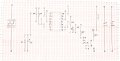
This is the new stripboard layout that I'm using for this circuit
CamScanner 11-03-2021 02.12.jpg
The schematic that I'm referring toK-010-sch.gif

I'm wasn't sure if my transistor connections are correct or wrong
 

AlbertHall

Joined Jun 4, 2014
12,640
P14 = 4.89 (value keep is declining)
This the battery voltage and it should be 9V.
Disconnect the speaker and check this voltage again. If it is still low then you need a new battery.
Leave the speaker disconnected and when you do get 9V repeat the other voltage measurements.
 

MrChips

Joined Oct 2, 2009
35,029
Your water sensor is not wired correctly. It should not be connected to GND.
You show no connection at IC1 pin-7.

Remove the 9V battery and check its voltage.
As Albert suggests, disconnect the speaker. Measure the voltage at pin-14 with the black lead of the DMM connected to the -ve rail.
 

absf

Joined Dec 29, 2010
1,968
Because you connected your sensor directly from positive 9V to GND, you are shorting the battery when you wet the sensor.

So your battery must be very week by now and need to replace with a new one. Check the 2 things what Mr Chips said that you should take care of.
 

Thread Starter

Hannan007_

Joined Oct 31, 2021
44
Your water sensor is not wired correctly. It should not be connected to GND.
You show no connection at IC1 pin-7.

Remove the 9V battery and check its voltage.
As Albert suggests, disconnect the speaker. Measure the voltage at pin-14 with the black lead of the DMM connected to the -ve rail.

ughhh, I was careless thanks for pointing that out cause you my circuit worked. It gave beeping sound when there's water detected on the sensor but the sound is not very loud but you can hear it clearly if u are close enough. I will post my new stripboard layout on this thread later.
 
Status
Not open for further replies.
Top