Facebook
 Google
 GitHub
 Linkedin

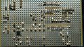
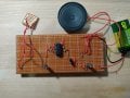
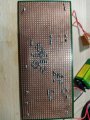
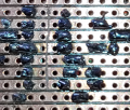
If you insist on wanting to use stripboard before testing your circuit on a solderless breadboard, here is what you need to know. As already pointed out, when you mount a DIP14 package, pin-1 is shorting to pin-14, pin-2 is shorting to pin-13, etc. You need to cut the tracks between these pairs of pins. If you are able to take advantage of this premade connection then you don't have to cut the track.
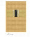
Look at the IC pinout of CD4011.
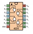
You will notice output on pin-3 is opposite input on pin-12.
Also output on pin-10 is opposite to input on pin-5.
You don't have to wire the CD4011 IC using the pins as designated in your original circuit diagram.
See if you can take advantage of the premade connections by rearranging the pin numbers of the IC.
Look at the IC pinout of CD4011.
You will notice output on pin-3 is opposite input on pin-12.
Also output on pin-10 is opposite to input on pin-5.
You don't have to wire the CD4011 IC using the pins as designated in your original circuit diagram.
See if you can take advantage of the premade connections by rearranging the pin numbers of the IC.