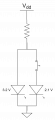
Turning 1 LED on and another off - I can't seem to make this schematic work.

Thread Starter

JustaJ0e

Joined Dec 14, 2022
6
While searching for information on how to turn one LED on while simultaneously turning another off, I found a similar thread with some very helpful diagrams. However, the original was for a 12v system and I am running off of 6v (2 coin cell batteries).
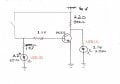
I have replicated the circuit but The best I can do is turn off LED(1).
LED(2) never comes on (I did test the LED itself. It is working).

Any clues as to where I am going wrong?
LED(1) is a 3mm red I believe has a 2.1 fwd v at 20ma I have protected with a 220ohm Resistor
LED(2) is a 5mm White, probably 3.4 fwd v at 20ma I have paired with 133ohm R
my other hardware is a micro switch and a 2N2222 with the 8.2k resistor on the base.

Thanks

View attachment 371958safe-LEDs-2.jpg
 
CR2032 coin battery is sized for about 3mA continuous current.

In your schematic when switch is on the circuit draws 50mA.

You must change the batter type.

But I am not sure whether this is your problem.
 

WBahn

Joined Mar 31, 2012
33,239
Remove the 8.2 kΩ resistor and just see if LED2 will work with just the switch, 133 Ω resistor, and LED. If it won't, then that's where to focus your efforts.

What, exactly, are the two coin cells you are using? CS2032? Something else? Don't expect them to last very long with a 20 mA current draw (more like 50 mA when the switch is closed). Most coin cells are intended for current draws on the order of 1% of that. At 20 mA, they will have significantly less capacity and are likely to drain well below their starting voltage in just a couple hours. For 2032s, they will probably be effectively dead in six to eight hours. As they drain, their internal resistance rises. Even fresh, they each probably have 10 Ω to 20 Ω, which is pretty significant for your circuit and is probably dropping close to a volt when the switch is closed.
 

sghioto

Joined Dec 31, 2017
8,756
If LED1 is functioning there's no reason why LED2 would not unless there's a connection issue.
Also suggest doubting the values of the LED resistors to extend battery life while testing.
 

Thread Starter

JustaJ0e

Joined Dec 14, 2022
6
Remove the 8.2 kΩ resistor and just see if LED2 will work with just the switch, 133 Ω resistor, and LED. If it won't, then that's where to focus your efforts.

What, exactly, are the two coin cells you are using? CS2032? Something else? Don't expect them to last very long with a 20 mA current draw (more like 50 mA when the switch is closed). Most coin cells are intended for current draws on the order of 1% of that. At 20 mA, they will have significantly less capacity and are likely to drain well below their starting voltage in just a couple hours. For 2032s, they will probably be effectively dead in six to eight hours. As they drain, their internal resistance rises. Even fresh, they each probably have 10 Ω to 20 Ω, which is pretty significant for your circuit and is probably dropping close to a volt when the switch is closed.
LED2 WILL work with just the switch, 133 Ω resistor as its own circuit but adding the 2n2222 back into the circuit (even with 0Ω trigger) stops LED2 from lighting up.

The run time on this device will be very short. A minute or so at a time and this circuit will be activated by a momentary switch. So it will be on for only a second or so at a time. The form factor of this prop REALLY calls for a small power source the size CR2032 so I'd really like to figure out a way to make this work.

Funny anecdote for any beginners (like myself) who are reading this. I am working on a hand prop (yes, halloween) and as I designed the electronics I continually tested each new iteration on the bench to see if it worked. Knowing I would only have room to power it with two CR2032 3v batteries, I powered my bench with 6 volts... from a phone charger.
TOTALLY OVERLOOKING THE WHOLE AMPERAGE THING! (puts face in hands)
SO I had this great thing that worked at 6v 1amp. Did not work at 6v (something) mA.

Rookie mistake. It's voltage AND current.
So I am once again at "re-design".
 

Thread Starter

JustaJ0e

Joined Dec 14, 2022
6
Also suggest doubting the values of the LED resistors to extend battery life while testing.
Great tip! Thanks.
Question: If my problem is that I am trying to pull more current than the batteries can deliver, will the larger resistors add to that problem?
 

sghioto

Joined Dec 31, 2017
8,756
No, the larger resistors will extend the battery life.
I don't recommend those batteries for the same reasons others have noted but good enough for now to figure out the problem with that circuit, unless they are almost spent.
 
Last edited:

WBahn

Joined Mar 31, 2012
33,239
LED2 WILL work with just the switch, 133 Ω resistor as its own circuit but adding the 2n2222 back into the circuit (even with 0Ω trigger) stops LED2 from lighting up.

The run time on this device will be very short. A minute or so at a time and this circuit will be activated by a momentary switch. So it will be on for only a second or so at a time. The form factor of this prop REALLY calls for a small power source the size CR2032 so I'd really like to figure out a way to make this work.

Funny anecdote for any beginners (like myself) who are reading this. I am working on a hand prop (yes, halloween) and as I designed the electronics I continually tested each new iteration on the bench to see if it worked. Knowing I would only have room to power it with two CR2032 3v batteries, I powered my bench with 6 volts... from a phone charger.
TOTALLY OVERLOOKING THE WHOLE AMPERAGE THING! (puts face in hands)
SO I had this great thing that worked at 6v 1amp. Did not work at 6v (something) mA.

Rookie mistake. It's voltage AND current.
So I am once again at "re-design".
I don't know what you mean by "0Ω trigger". Please explain.

Are you POSITIVE that the base resistor is actually 8.2 kΩ? Have you measured it?

Try using your original circuit but remove the 220 Ω resistor. Does LED2 now work?

If so, the problem is probably that the current in the first side goes up considerably when you close the switch.

With the switch open, the current in the 220 Ω resistor is about (6 V - 2.1 V) / 220 Ω which is 18 mA.

With the switch closed, the current in the 220 Ω resistor goes to 6 V / 220 Ω which is 27 mA, while the current in the 130 Ω resistor is about (6 V - 3.2 V) / 130 Ω = 22 mA, giving you a total current draw of right around 50 mA.

It's actually going to be less than that because of the loading on the batteries via the internal resistance.

To get an idea of how bad the loading is, I took two fresh CS2032 batteries and a 120 Ω resistor, which would nominally yield a current draw of 50 mA.

The unloaded voltage was 6.53 V. As soon as I connected the resistor, the voltage dropped to 5.25 V. But then it continued to drop and 10 seconds was 4.97 V. It continued to drop at about 7 mV/s and, after 60 seconds, was down to 4.52 V. At that point I released the resistor and the voltage went to 5.62 V and started to recover slowly. After another 60 seconds and it was 5.72 V. After five minutes it was back to 5.96 V. If you were getting something similar, then your current in LED2 would be significantly (though I would still expect it to light up at least somewhat).

First thing to do is determine how much current you really need in the LEDs in order to get them to work adequately for your prop. You might be surprised how little you need. If 20 mA is bright enough, there's a pretty good chance that 10 mA will also work.

One quick way to reduce the current is to put another resistor in the collector of the transistor. You don't need to get the voltage across LED1 all the way down to zero, you just need to get it well below the 2.1 V it needs to light up. To get it down to, say, 1.5 V, the 220 Ω resistor has to drop at least 4.5 V, which requires a current of 20 mA. The Vcesat of the transistor at this current is going to be pretty low, but let's call it 200 mV to be safe. That means that the total resistance only needs to be about 290 Ω. Try putting a 100 Ω resistor between the 220 Ω and the collector.

But it would be better yet if we didn't have to shunt current around LED1 in the first place, and instead could simply steer the current to either go through one LED or the other. So let's see what that might look like.

The obvious way to do this is to just use a SPDT momentary switch.
1791178539652.png
You will probably find that a single resistor will work just fine, but if not, simply put separate resistors in series with each LED. You should be able to get SPDT pushbutton momentary switches the same size, or close enough, to the switch you are using.

If, for some reason (that I have a hard time imagining), you have to use a SPST switch, the you can leverage the difference in forward voltages. Notice what happens if you put both LEDs in parallel along with a single resistor to the power supply. Only the lower voltage LED lights because it clamps the voltage across the other was at too low a voltage for it to light up. So now you can just use your switch to turn it on and off and the other will turn on automatically.

1791179307619.png
 

MisterBill2

Joined Jan 23, 2018
28,371
Finally in post #10 I see a circuit that is more efficient!
OF COURSE, those coin cells will not last very long no matter how efficient the circuit is. The posts about THAT are correct!
 

Thread Starter

JustaJ0e

Joined Dec 14, 2022
6
I don't know what you mean by "0Ω trigger". Please explain.

Are you POSITIVE that the base resistor is actually 8.2 kΩ? Have you measured it?
(snip)
Wow! That’s lots of great stuff.

First thing, 0 ohm. Sorry for that. When you said to remove the resistor I assumed that meant to keep the circuit. So I replaced the resistor with a jumper wire. I referred to it as 0 ohm.

The 8.2 kΩ resistor is too large a value for my meter to read. The color bands identify it as such and it comes on a strip of identical resistors so I trust it is close to its label. I can say my other resistors from the same supplier all read .01 over what they are labeled as. All being said, I believe my resistors to be as labeled.

SPDT switch - YES. If only I could find a small enough switch of this variety. This was my very first thought for doing this but I couldn’t find a momentary SPDT with the size of a micro switch (aprox. 6mm x 6mm x 4mm). I also searched for a NC micro switch (the idea being to turn off LED1 thus giving LED2 enough V to turn on.) but couldn’t find that either.

That is some extensive testing you did of the 2032 cells and what the current draw is doing to them! I still may be able to cludge them into working but I am going to see how hard it will be to re-do the 3D models to fit a 9v battery in there.

Test results.

  • Original circuit minus 220Ω (also minus LED1 as I believe it would burn out without the resistor). LED2 does not function.
  • Tried the single resistor circuit With LED1 and my NO micro switch on one leg and LED2 connected directly on the other leg. This worked but was the opposite effect than I need.
  • Swapped the LED in the above circuit and LED1 would come on but LED2 would never light. Added a 100Ω resistor to LED1 leg and now LED2 DID light up but LED1 would only dim. Tried swapping the 100Ω resistor with other values but the circuit would only work with the 100Ω resistor.

I appreciate all this direction and info.

While my mistakes are frustrating (as far as getting this project complete) they are how a best learn. I can (and have) read the text of how all this works but that doesn’t seem to stick as well with me as physically touching components and making them work… Or more often, breaking things and then going thru and seeing what I did wrong.

For some reason THAT is always the lesson that sticks with me the best.
 

WBahn

Joined Mar 31, 2012
33,239
Wow! That’s lots of great stuff.

First thing, 0 ohm. Sorry for that. When you said to remove the resistor I assumed that meant to keep the circuit. So I replaced the resistor with a jumper wire. I referred to it as 0 ohm.
Remove means REMOVE. Not short it out. That will ensure that it won't work and rapidly drain the battery, assuming it doesn't kill the transistor first (which it may not given the internal resistance of the coin cells). Just disconnect one end of the resistor to remove it from the circuit.

The 8.2 kΩ resistor is too large a value for my meter to read.
What meter are you using? You probably want to get a different meter, since this is a very common resistance value for electronic projects. Everything up to ~1 MΩ is commonly used (and up to 10 MΩ is far from unusual). I just picked up meters from Amazon for under $5 and testing shows that they yield results very close to my Flukes (in fact, I couldn't claim which ones are closest to the correct values).

SPDT switch - YES. If only I could find a small enough switch of this variety. This was my very first thought for doing this but I couldn’t find a momentary SPDT with the size of a micro switch (aprox. 6mm x 6mm x 4mm). I also searched for a NC micro switch (the idea being to turn off LED1 thus giving LED2 enough V to turn on.) but couldn’t find that either.
DigiKey carries them in 6mm x 6mm outline. They also carry SPST tactile switches in both NO and NC (as well as a SPDT switch with one NO and the other NC).

Test results.

  • Original circuit minus 220Ω (also minus LED1 as I believe it would burn out without the resistor). LED2 does not function.
  • Tried the single resistor circuit With LED1 and my NO micro switch on one leg and LED2 connected directly on the other leg. This worked but was the opposite effect than I need.
  • Swapped the LED in the above circuit and LED1 would come on but LED2 would never light. Added a 100Ω resistor to LED1 leg and now LED2 DID light up but LED1 would only dim. Tried swapping the 100Ω resistor with other values but the circuit would only work with the 100Ω resistor.

I appreciate all this direction and info.
If you REMOVE the 220 Ω resistor, then there's no way for current to flow through LED1.

Putting the switch in the other leg won't work because you need to switch the LED that has the lower Vf.

For some reason THAT is always the lesson that sticks with me the best.
Learning from our mistakes is generally the most effective way to learn, provided we survive them.
 

MisterBill2

Joined Jan 23, 2018
28,371
This thread is not making any sense at all!!!
The Thread Starter needs to clearly state what thepurpose is. AND THEN state what any additional conditions and requirements. In addition I need to contact a source of anti-virus code that is a source I can trust.
 

WBahn

Joined Mar 31, 2012
33,239
This thread is not making any sense at all!!!
The Thread Starter needs to clearly state what thepurpose is. AND THEN state what any additional conditions and requirements. In addition I need to contact a source of anti-virus code that is a source I can trust.
I don't know what isn't making sense. The TS is making a Halloween prop. When turned on, it has two different colored LEDs exactly one of which is one. A momentary switch controls which one it is. He is very space-constrained so he wants to use just two CS2032 coin cells for power and a very small (looking at a 4mm x 4mm) tactile switch. What else does he need to state for it to make sufficient sense?

And what does your need to contact a source of anti-virus code have to do with the thread, whether they can be trusted or not???
 
OK, now it is a bit clearer! My Mind-reading ability is VERY POOR!! using those two CR2032 coin cells in a stack will work but only for a while. Probably TWO push-button or other momentary switches will be the way to go. If a bit more size will work, two AA or A, or AAA cells will be brighter and last linger. And cost a lot less.
 
Top