 Facebook
 Google
 GitHub
 Linkedin
Hello, I need help with a school project.
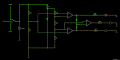
I have a working Falstad simulation and I would like to turn it into a PCB layout, preferably in KiCad.
The circuit is a voltage monitor using an LM324 and three LEDs.
Required behavior:
My PCB requirements:
I have a working Falstad simulation and I would like to turn it into a PCB layout, preferably in KiCad.
The circuit is a voltage monitor using an LM324 and three LEDs.
Required behavior:
- at 10.7 V only the yellow LED should turn on
- at 12 V only the green LED should turn on
- at 14.5 V only the red LED should turn on
- only one LED should be on at a time
- LM324, using 3 of the 4 op-amps
- 3 LEDs with 560 ohm series resistors
- 4.7 V Zener diode
- 2 × 1N4148 diodes
- several resistors as voltage dividers
- input selection for 10.7 V / 12 V / 14.5 V
My PCB requirements:
- single-sided PCB
- board size: 40 × 100 mm
- LM324 as DIP-14
- all components from the Falstad simulation should be on the PCB, except the voltmeter
- the 3 LEDs should be on the PCB
- 3 input pads for 10.7 V / 12 V / 14.5 V
- 4.7 V Zener diode and the two 1N4148 diodes should be included
- I want to avoid crossing tracks as much as possible
- wire jumpers are okay if needed
- I would like to avoid 90-degree track corners
Attachments
-
 62.4 KB Views: 11


