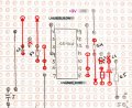
I got this new schematic and I've tried to construct it on the stripboard

Status
Not open for further replies.

dl324

Joined Mar 30, 2015
18,449
I've checked the polarity using the multimeter, it shows that the black wire is positive (+) and red is negative (-)
If that's the battery voltage, that's not good for a 9V battery.
sorry but I don't quite catch up on how to test the pins, can u tell me what what topic I should search for to test out the IC pins?
You measure the voltage between circuit ground and each of the pins. When the output of the gate is HIGH, it should be very near the battery voltage. When they're LOW, the voltage should be near 0V. A pin diagram was given in an earlier post.
 

MrChips

Joined Oct 2, 2009
35,032
A 9V battery should show close to 9V on a voltmeter. Red is positive. Black is negative. You have the battery connected backwards and it is dead.
 

Thread Starter

Hannan007_

Joined Oct 31, 2021
44
If that's the battery voltage, that's not good for a 9V battery.
You measure the voltage between circuit ground and each of the pins. When the output of the gate is HIGH, it should be very near the battery voltage. When they're LOW, the voltage should be near 0V. A pin diagram was given in an earlier post.
unfortunately there's no voltage/current flow after it get through R6
 

Thread Starter

Hannan007_

Joined Oct 31, 2021
44
A 9V battery should show close to 9V on a voltmeter. Red is positive. Black is negative. You have the battery connected backwards and it is dead.
is my IC dead? I have troubleshoot the IC to make sure if my IC is dead or not based on this video
 

absf

Joined Dec 29, 2010
1,968
Based on the PCB back side of post #9, I found the following mistakes...

The wire between P5-P6 and P3 is missing. R2 and C3 should be connected to an unused row instead of P3.

The wire between P8-P9 and P11 is also missing. R4, R3 and C3 should be connected to an unused row instead of P11.


There could be some mistakes on how the 2 transistors are connected, I have not check that yet.
 
Last edited:

Thread Starter

Hannan007_

Joined Oct 31, 2021
44
how can I connect the components to to IC pins if its move to the unused row. Based on the schematic, the components are connected to the certain pins on the IC. If I'm not mistaken on the schematic P2 and P3 should be connected right? And how can I solder three vertical points like P8-P9 and P11. should I juts solder the P8 and P9 without jumper and used a jumper to connect P9 and P11?
 
Last edited:

MrChips

Joined Oct 2, 2009
35,032
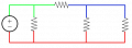
You need to understand what is a node in a circuit.

1635754964536.png

In the diagram above, there are three nodes identified in three different colours, red, green and blue.
All the components connected to the red node share a common potential within the circuit. The red lines represent wire connections with zero ohms (usually copper wires and PCB tracks or traces). The same thing goes for the green and blue nodes.

On your stripboard you do the same thing. You connect all the components that share a common node using the stripboard tracks or jumper wires. In does not matter where on the stripboard these tracks are located. Furthermore, a node may occupy multiple tracks if you place a jumper from track to track, in other words, make sure that you make electrical conductivity from track to track for the same node. In other words it does not matter where the IC pin is located so long as it is connected to a track that forms a common node.

At the same time, make sure that each node is isolated from all the other nodes.
 

MrChips

Joined Oct 2, 2009
35,032
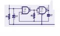
As an example, have a look at your original circuit.
Rain sensor_3.jpg

IC1 pins 3, 5, 6 and one leg of R2 share a common node.
Make sure that there is copper connection with these four points and with nothing else.

Similarly, pin-2, the other leg of R2 and one leg of C2 share another node.
These three must be connected to a common track and nothing else.
 

MrChips

Joined Oct 2, 2009
35,032
how can I connect the components to to IC pins if its move to the unused row. Based on the schematic, the components are connected to the certain pins on the IC. If I'm not mistaken on the schematic P2 and P3 should be connected right? And how can I solder three vertical points like P8-P9 and P11. should I juts solder the P8 and P9 without jumper and used a jumper to connect P9 and P11?
I don’t see pin-2 connected to pin-3 in the schematic.
 

Thread Starter

Hannan007_

Joined Oct 31, 2021
44
Can I solder directly to the resistor to extend the connection cause I can't use jumper cause I don't want to de-solder the circuit just to make a space for a jumper
 

absf

Joined Dec 29, 2010
1,968
I'm afraid you'd have unsolder one leg of R2 and C2 and extend the legs to the unused row. Same thing goes with C3,R3 and R4.

BTW, I missed out one jumper from P2 to the upper unused row....:p
 

MisterBill2

Joined Jan 23, 2018
28,051
Now is a time to check the battery with the meter with the battery disconnected from the circuit. I hope hat the + and - are marked on the battery, that will make it simple to know which should be positive and negative. An unused battery should show about 9 volts with nothing connected,
Then see which terminal on the battery connector goes to the positive terminal on the battery. This will be the basis of the next check, done using the resistance range of the meter. With the meter on the 2K or 20K range, there should be not much resistance between the battery connector positive terminal and pin #14 on the IC connector. It should be less than 5 ohms. Then check the resistance between the battery connector negative terminal, it should also be less than 5 ohms. This check will verify that either the battery connector is correct or if it is reversed.
 

Alec_t

Joined Sep 17, 2013
15,149
It looks as though one or two stray solder blobs could be bridging adjacent tracks. Check the board with a magnifier and/or meter for inadvertent short circuits.
 

Thread Starter

Hannan007_

Joined Oct 31, 2021
44
I'm afraid you'd have unsolder one leg of R2 and C2 and extend the legs to the unused row. Same thing goes with C3,R3 and R4.

BTW, I missed out one jumper from P2 to the upper unused row....:p
yup I have unsolder R2 and C2 then I connect it to the unused row and which is the row I put P2 jumper......and I did the same thing with C3, R3 and R4
 

Thread Starter

Hannan007_

Joined Oct 31, 2021
44
It looks as though one or two stray solder blobs could be bridging adjacent tracks. Check the board with a magnifier and/or meter for inadvertent short circuits.
if its connect to the adjacent tracks, can I just cut the track or is there other ways instead of that ?
 

Thread Starter

Hannan007_

Joined Oct 31, 2021
44
Now is a time to check the battery with the meter with the battery disconnected from the circuit. I hope hat the + and - are marked on the battery, that will make it simple to know which should be positive and negative. An unused battery should show about 9 volts with nothing connected,
Then see which terminal on the battery connector goes to the positive terminal on the battery. This will be the basis of the next check, done using the resistance range of the meter. With the meter on the 2K or 20K range, there should be not much resistance between the battery connector positive terminal and pin #14 on the IC connector. It should be less than 5 ohms. Then check the resistance between the battery connector negative terminal, it should also be less than 5 ohms. This check will verify that either the battery connector is correct or if it is reversed.
I've tested it out , I got no reading on the first test with the meter on 2k and 20k rage it shows 0. The second test, which is negative terminal of the batt connector and pin 14. I got 0.21 with 2k range. Does it means my battery connector is reversed?
 

Thread Starter

Hannan007_

Joined Oct 31, 2021
44
I'm afraid you'd have unsolder one leg of R2 and C2 and extend the legs to the unused row. Same thing goes with C3,R3 and R4.

BTW, I missed out one jumper from P2 to the upper unused row....:p
the circuit still doesnt work. I'm trying to figure out if the battery connector is reversed or not
 

Thread Starter

Hannan007_

Joined Oct 31, 2021
44
I used a new battery and new connector then I change the polarity of the battery connector. and the circuit worked perfectly except the buzzer is not loud but it is okay as long as the circuit worked as I want. Thanks a lot too all of person who helped me I've learned many things from you guys and I dont think the circuit will worked if I didnt used this website. Sending love and virtual hugs to all of you. I'm gonna cry lol.

Edit: I think the battery have short circuit as it's getting hot and one of the resistor is broken which is R3. Fortunately, the IC still works. If I put the battery on reversed, it'll short circuit. but if I put the battery in original polarity, the circuit doesn't worked.
 
Last edited:
Status
Not open for further replies.
Top