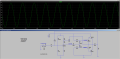
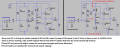
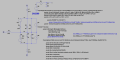
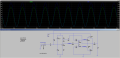
You can really sink a lot of time tweaking this. Here is a version with 2N3904/6 only. The transistors are at maximum of 422 mW dissipation. I hope there is nothing burning in this schematic.
The simulation shows 422 mW dissipation on the last pair of output transistors into 8 ohms. However, current was at 1.2 Amperes maximum. What is a good transistor to handle this?
I didn't read all the posts so I hope someone didn't wrote this.
When the base is high, the transistor conducts. If you have only 1 resistor Vcc to collector, this is the time when there will be voltage over the resistor, because if the transistor does not conduct, no current will flow.
On the other hand normally there should be a load after the resistor and before the collector. The second end of the load is connected to ground. That way when the transistor conducts (base high), the current will pass through the transistor to ground, the load will not have much current through it, but when you start lowering the base voltage, the current will start passing through the load instead of through the transistor to ground. This makes them out of phase on 180 degrees.
Chris:
I did not see anyone mention this in this thread so i'll make a note now.
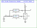
The simplest model of a transistor is a current controlled current source (CCCS). The base current is the sense current of the CCCS and the collector current is the output current of the current source. This gets you pretty far with amplifier circuits.
Next comes the base emitter diode. If you measure an NPN transistor base emitter alone, it looks like a diode. So using a diode we can model the base emitter diode and thus we see some voltage drop as twe apply base current.
If we measure the transistor with an Ohm meter, we note that we see two diodes. One is the base emitter diode and the other is the base collector diode. The base collector diode doesnt do much in the active region, but when the transistor enters saturation it proivdes feedback to the base and that prevents the collector voltage from going to exactly zero.
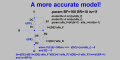
So the simplified but very useful model is a current controlled current source and two diodes.
In the diagram the two diodes are shown and their typical equations, and two resistors but you can easily add an emitter resistor too. The two didoes are drawn in very light green so as not to hide the two equations.
Here is a version with 2N3904/6 only. The transistors are at maximum of 422 mW dissipation. I hope there is nothing burning in this schematic.
The simulation shows 422 mW dissipation on the last pair of output transistors into 8 ohms. However, current was at 1.2 Amperes maximum.
Why didn't you read the datasheets that say, "Maximum current= 200mA"?
With a 25V supply, the output swing into 8 ohms is about 23V p-p which is 8.13V RMS. Then the power in the 8 ohms load is (8.13V squared)/8 ohms= 8.2W. A class AB amplifier at its maximum output swing is about 50% efficient so the output transistor pair heat with about 4.1W which is 2.05W each. the 2N3904 and 2N3906 are low power so they cannot use a heatsink and their maximum allowed heating is 0.625W each.
I would use TIP31 and TIP32 power transistors.
There is another way to get a larger output current. It is to use the inclusion of transistors in parallel. To equalize the transistor currents, use resistors in the emitter. Set the voltage on these resistors (in the absence of a signal) ~ 100mV. For your case, enough is enough for 10 transistors on the shoulder. And the bonus: you can not put radiators cooling. In addition, low-power transistors have better frequency properties. In the history there were circuits of amplifiers and stabilizers with the number of transistors reaching 600 pieces.
I opt for at least some simplicity when i do these without a simulator and when trying to show how the basic transistor works without going into complete detail.
I opt for at least some simplicity when i do these without a simulator and when trying to show how the basic transistor works without going into complete detail.
I am happy you brought these other models into the picture too so other readers can look at the options they have.
In the simplified EM model they run the current source through the 'be' diode too. I sometimes do that and sometimes just leave the diode for the base current only in a slightly different approximate model. I dont usually look for superb accuracy in transistor models because of the variations that occur in practice, but i do like the model to show some of the basic functionality so a given circuit can be studied.
Hi Chris,
If you want to keep the transistors in the 400mW range, then if you made the VCC around 11V max. you'll dissipate around 400mW, across each transistor.
I formulated audiogurus steps in solving for Pdiss. across the transistors, post #148 , and came up with this equation.
Assuming a ratio of (VCC / 1.1) for Vp-p.
" PQ" = chosen value of Pdiss. across each output transistor.
Equation : [VCC = { 2.2 x ( 32 x PQ)^2 / 0.707 }]
Choose a "PQ" value you would like to have your transistor to work at, and plug it in to the equation.
Thanks guys, I will be able to have time to work on this again this weekend. I am thinking of turning it into an actual project. I just have a few questions right now.
Q1. Is this amplification practical for a desktop speaker that needs to be connected to the line out of a PC sound card? I am thinking of reducing Vcc to 12 volts as I have one of those adapters around. This would mean amplification of 2 volt peak to peak to 10 volts peak to peak. I am assuming 1 volt peak is the average output voltage of PC line out. If these are the wrong parameters, please recommend.
Q2. Can you guys recommend a cheap oscilloscope probably less than 100 dollars that would work with 110 - 240 volts power mains? I'm not sure what features are important.
Thanks guys, I will be able to have time to work on this again this weekend. I am thinking of turning it into an actual project. I just have a few questions right now.
Q1. Is this amplification practical for a desktop speaker that needs to be connected to the line out of a PC sound card? I am thinking of reducing Vcc to 12 volts as I have one of those adapters around. This would mean amplification of 2 volt peak to peak to 10 volts peak to peak. I am assuming 1 volt peak is the average output voltage of PC line out. If these are the wrong parameters, please recommend.
Q2. Can you guys recommend a cheap oscilloscope probably less than 100 dollars that would work with 110 - 240 volts power mains? I'm not sure what features are important.
There is one around 20 dollars (USD) on Amazon and sites like that. It is just a PC board with LCD display and jacks and buttons but it works as a scope. It is made from a ARM Cortex CPU.
The bandwidth is limited at around 100kHz, but it seems good enough for audio. It's only one channel though.
Works good for looking at remote control signals too using a IR detector diode.
Runs on 9 to 12 volts DC so you can even use batteries if you like.
If you want dual channel or just better than that you could look at the PC scopes from maybe 100 dollars USD up.
Other than that, you start to move into the 300 dollar (USD) range.
@hobbyist
The hantek seems to be the most cost effective choice at this time. I am still trying to decide. One point of consideration is linux compatibility as I don't use Windows except for tax software. @Audioguru
You recommended tip31 and tip32. The Ic on the output transistor goes from 0 to 1.2 A. Looking at the datasheet for tip31/32, it seems the hfe varies with the Ic range from 40 to 150 unless I read it wrong. Is it important to have the hfe be as flat as possible on the graph for the range of Ic ? @Bordodynov
Would the use of multiple output transistors on the shoulder pose a challenge as far as each one will likely have different hfe's? I think you proposed to put an emitter resistor to each transistor so that each transistor will output the same current, negating the difference in hfe's. This would seem an arduous task the more transistors are used.
I think I figured out how the base bias resistor on the push pull stage set the base current. I think this is the formula:
Iinput = (Vcc – Vbe / (Req + Re*hfe)) /2 ( Its close but I am not considering the internal emitter resistor here )
where Req is the equivalent resistance of the base resistors which are considered to be in parallel and Re is the speaker impedance. Iinput is the base current at quiescence. Interestingly, with use of base voltage divider bias, the ceiling of input impedance for each half of the push pull stage ( I am only analyzing one half of the push pull stage because i consider the other half turned off ) seems to be equal to the value of the base resistor ( not Req ). I guess this is because each base resistor is parallel with a high impedance transistor base resistance so their parallel equivalent is equal to the value of the base resistor.
The hFE is current gain, not voltage gain. You just need enough base current for transistors that have minimum current gain.
The TIP31 has a minimum current gain of 25 at a collector current of 1A and maybe 23 at 1.2A. Then the base current is 1.2A/23= 52mAand the minimum current gain of its driver in a darlington or Sziklai is about 80 for a total of 1840, not the 1 million that you show. When the speaker current is 1.2A then the base current is 1.2A/1840= 0.65mA. Then your 8.5k base bias resistor can pull the base up to only 5.5V which is not good enough unless the transistors have much higher current gain or if the 8.5k resistors are 4.7k.
Again, you are driving the diodes, not the transistors. The diodes also need current so the 4.7k resistors will not be low enough to provide all the current that is needed.
Sorry, I wasn't very clear. The schematic above was just a demonstration of the effect of hfe values to the midpoint voltage of the push pull stage. I simply put in a high enough bogus hfe so that it will not be dragged down. I should not have said Darlington or sziklai. What I meant was multiple transistors where you can multiply each level of hfe with the next and even multiple transistors on the shoulder and with possibly different transistor types. In my LTspice simulation, I did put in a 2n3904 (hfe 300) and then attached to it a tip32 (hfe 23) as the second level or output transistor. Going by your calculations then, at 1.2 A, the base current would be 1.2/(300*23) = 0.0001739. Then you multiplied the 8.5k resistor with the base current to arrive at 5.5 volts. In this case it would be 0.0001739 * 8500 = 1.478 volts. Then you recommended a base resistor of 4.7k so presumably the intended voltage was arrived at by .65÷1000×4700 = 3 Volts. Then that should be 0.0001739 * 4700 =0.81733 volts. I failed to understand what you meant by "is not good enough" . Also the base current is not the same as the base resistor current as this is a voltage divider bias. The equivalent base resistor is half the value of the base bias resistor at around 4250. Can you clarify?
Also, will it be better to keep the operation of the amplifier on the flat portion of the hfe vs Ic plot? In which case I would need a transistor with hfe remaining almost constant between 0 and 1.2 A? I am just thinking that different hfe's at different points of Ic would result in an output sine wave that is not proportionally amplified with respect to the source.
I think now what you meant probably is that the base voltage couldn't go close enough to Vcc in the case of the top half of the sine wave if the base current was not low enough.

 Facebook
 Google
 GitHub
 Linkedin