CD4033 Connections For 0 To 9 Counter

Thread Starter

maker_2023

Joined Nov 20, 2023
199
Remember this rule - Leave no input pin not connected. In other words, input pins must be connected to a proper logic level voltage.

Pin-15, CLK is an input pin. What are you going to do with that? Connect it to pin-15 of the previous counter.

Since RST, pin-9 is active HIGH, connect it to GND to disable RST (or connect it to pin-9 of the previous counter).
Thanks. It works perfectly! Now to wire up the other four digits.
M
 
Last edited:

Thread Starter

maker_2023

Joined Nov 20, 2023
199
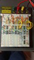
I have now added a third digit to the counter circuit. As luck would have it, the third digit doesn't
work at all but one and two work fine. I have checked the wiring multiple times and I believe that
it is correct. I swapped out the CD4510, the CD4511 and the display with those in the second stage.
All ICs work. I checked the voltages on CD4511 and they are correct. I have no idea what to do next.
Note: I have disconnected all segments except for "e" so that the photo is easier to view.

Help!

M
 

Attachments

Last edited:

eetech00

Joined Jun 8, 2013
4,716
I have now added a third digit to the counter circuit. As luck would have it, the third digit doesn't
work at all but one and two work fine. I have checked the wiring multiple times and I believe that
it is correct. I swapped out the CD4510, the CD4511 and the display with those in the second stage.
All ICs work. I checked the voltages on CD4511 and they are correct. I have no idea what to do next.
Note: I have disconnected all segments except for "e" so that the photo is easier to view.

Help!

M
Show a schematic.
 

sarahMCML

Joined May 11, 2019
703
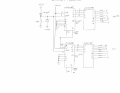
Here is a schematic for the 2-digit version. The hundreds digit is wired identically
to the tens digit. Pin 1 of the CD4510s is grounded, contrary to what the schematic shows.
I may be wrong, but it looks to me as if pins 1 & 16 on the leftmost counter may not be inserted into the breadboard?
 
Top