You don't mention what is generating the clock or what the forward voltage of the LED is.
If you take the time to read the datasheets, they'll give you the information you need.
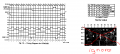
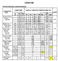
From the TI datasheet: View attachment 314542 View attachment 314543
The counter increments on the rising edge of the clock. With a 5V supply, a high level input voltage must be at least 3.5V.
Thanks!
If you were using a red, green, or yellow LED, the forward voltage is probably less than 3.5V.
Input signals greater than 1.5V but less than 3.5V will give unpredictable results.
1a) To satisfy input requirements
All inputs, especially inputs with high impedances, require a load on the input otherwise the input becomes an antenna susceptible to random interference. What value resistance to use? You need to know the input voltage and current characteristics in order to determine the range of acceptable values. The calculation is done using Ohm's Law.
Never leave inputs with no connection (NC) to a proper logic voltage level.
1b) For switched inputs
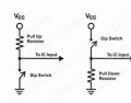
For a low side switch, you need a pull-up resistor. For a high side switch, you use a pull-down resistor. The resistance value is determined the same way as for (1a).
2) When the gate output is open-collector or open-drain
Open-collector (BJT gates) and open-drain (CMOS gates) do not source current. They only sink current. A pull-up resistor supplies source current when a logic HIGH output is desired. Totem-pole (push-pull outputs) can both source and sink current. They do not need additional resistor loads.
Many if not most analog comparator ICs have open-collector outputs.
3) To match the impedance of the transmission line
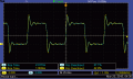
In high and very high frequency applications, it is important that transmission lines are properly terminated with the correct resistive load. If not properly terminated, the signals will be degraded with reflections on the transmission line. This will be observed on the oscilloscope as "ringing" or oscillations after the leading and trailing edges or a square wave.
4) Bias resistors in networks
RS-485 networks, for example, require both transmission line termination and proper DC bias voltages on the A and B lines.
Hence pull-up, pull-down, and termination resistors are required.
1a) To satisfy input requirements
All inputs, especially inputs with high impedances, require a load on the input otherwise the input becomes an antenna susceptible to random interference. What value resistance to use? You need to know the input voltage and current characteristics in order to determine the range of acceptable values. The calculation is done using Ohm's Law.
Never leave inputs with no connection (NC) to a proper logic voltage level.
1b) For switched inputs
For a low side switch, you need a pull-up resistor. For a high side switch, you use a pull-down resistor. The resistance value is determined the same way as for (1a).
2) When the gate output is open-collector or open-drain
Open-collector (BJT gates) and open-drain (CMOS gates) do not source current. They only sink current. A pull-up resistor supplies source current when a logic HIGH output is desired. Totem-pole (push-pull outputs) can both source and sink current. They do not need additional resistor loads.
Many if not most analog comparator ICs have open-collector outputs.
3) To match the impedance of the transmission line
In high and very high frequency applications, it is important that transmission lines are properly terminated with the correct resistive load. If not properly terminated, the signals will be degraded with reflections on the transmission line. This will be observed on the oscilloscope as "ringing" or oscillations after the leading and trailing edges or a square wave.
4) Bias resistors in networks
RS-485 networks, for example, require both transmission line termination and proper DC bias voltages on the A and B lines.
Hence pull-up, pull-down, and termination resistors are required.
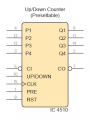
Pins 3, 4, 12 and 13 preset pins are floating right now. I looked at the data sheet and
I can't see where it says whether they should be a high or low logic level when up-
counting.
What logic level should they be at and are resistors needed?
What would the input current and voltages be in order to calculate the reistor values?
Think of input as your ear and output as your mouth. You don't want to stuff something in your mouth and gag.
Pin-7 carry-out is an output. Never connect outputs to Vcc or GND. Leave them not connected.
Pins 3, 4, 12 and 13 preset pins are floating right now. I looked at the data sheet and
I can't see where it says whether they should be a high or low logic level when up-
counting.
Assuming VDD = 5V
We are focusing on data (in yellow boxes) at +25°C
Input Low Voltage VIL Max = 1.5V
Input High Voltage VIH Min = 3.5V
Input Current IIN Max = 0.1μA
In order to present a logic LOW input, pull-down resistor R = VIL / I = 1.5V / 0.1μA = 15MΩ
In order to present a logic HIGH input, pull-up resistor R = (VDD - VIH) / I = (5V - 3.5V )/ 0.1μA = 15MΩ
You can see that you have a very wide range of resistance values to use.
10k - 100kΩ will work fine for CD4000 type CMOS gates.
View attachment 314842
Assuming VDD = 5V
We are focusing on data (in yellow boxes) at +25°C
Input Low Voltage VIL Max = 1.5V
Input High Voltage VIH Min = 3.5V
Input Current IIN Max = 0.1μA
In order to present a logic LOW input, pull-down resistor R = VIL / I = 1.5V / 0.1μA = 15MΩ
In order to present a logic HIGH input, pull-up resistor R = (VDD - VIH) / I = (5V - 3.5V )/ 0.1μA = 15MΩ
You can see that you have a very wide range of resistance values to use.
10k - 100kΩ will work fine for CD4000 type CMOS gates.
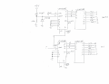
I now have the 10s digit counter stage wired up. It just displays a zero while the units stage counts
to 9. I connected the "Carry Out" of stage 1 to the "Carry In" of stage 2. Not sure what to do with
pin 9 (Reset) of the stage 2 counter. Schematic attached.
View attachment 314842
Assuming VDD = 5V
We are focusing on data (in yellow boxes) at +25°C
Input Low Voltage VIL Max = 1.5V
Input High Voltage VIH Min = 3.5V
Input Current IIN Max = 0.1μA
In order to present a logic LOW input, pull-down resistor R = VIL / I = 1.5V / 0.1μA = 15MΩ
In order to present a logic HIGH input, pull-up resistor R = (VDD - VIH) / I = (5V - 3.5V )/ 0.1μA = 15MΩ
You can see that you have a very wide range of resistance values to use.
10k - 100kΩ will work fine for CD4000 type CMOS gates.
I now have the 10s digit counter stage wired up. It just displays a zero while the units stage counts
to 9. I connected the "Carry Out" of stage 1 to the "Carry In" of stage 2. Not sure what to do with
pin 9 (Reset) of the stage 2 counter. Schematic attached.
No. 15MΩ is the maximum limit.
But you don't want to go there.
What is the minimum value? The minimum is 0Ω.
Hence your range of suitable resistance is 0-15MΩ.
0Ω is considered a short circuit and absolutely nothing wrong with this except that there is no excessive current protection if something goes wrong.
It is best to stay within a modest range such as 1k - 100kΩ.
I now have the 10s digit counter stage wired up. It just displays a zero while the units stage counts
to 9. I connected the "Carry Out" of stage 1 to the "Carry In" of stage 2. Not sure what to do with
pin 9 (Reset) of the stage 2 counter. Schematic attached.
No. 15MΩ is the maximum limit.
But you don't want to go there.
What is the minimum value? The minimum is 0Ω.
Hence your range of suitable resistance is 0-15MΩ.
0Ω is considered a short circuit and absolutely nothing wrong with this except that there is no excessive current protection if something goes wrong.
It is best to stay within a modest range such as 1k - 100kΩ.

 Facebook
 Google
 GitHub
 Linkedin