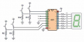
CD4033 Connections For 0 To 9 Counter

MrChips

Joined Oct 2, 2009
34,974
Hi Dennis:

I have now tried the circuit and it doesn't work. I have tested the clock portion of the circuit and it works. I tested the CD4511BE and the
Display prior to building the circuit and they work. I am wondering about the inputs.

M
It is so easy for one to say "it doesn't work" because for the end user that is all they care about.
There is always the opportunity to give more information in order to assist in trouble shooting.

For example, one could add:
"The display shows a constant 0 (or whatever) but does not advance even though I have given the counter a valid input clock pulse".
 

Thread Starter

maker_2023

Joined Nov 20, 2023
199
How do you know "it doesn't like that"?
Does it make a quick dash to the toilet?

Read my previous post.
HI:
Ya it almost knocked me over making the dash. LOL. All segments are lit up.
The lamp test pin 3 is grounded. If I remove the ground connection for
pin 3, none of the segments light.
M
 

MrChips

Joined Oct 2, 2009
34,974
HI:
Ya it almost knocked me over making the dash. LOL. All segments are lit up.
The lamp test pin 3 is grounded. If I remove the ground connection for
pin 3, none of the segments light.
M
Ah, that's better.
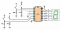
Remove the ground connection to pin-3.
Connect pin-3 and pin-4 to +5V.
Connect pin-5 to GND.
Put 1k-10kΩ pull-down resistors on pins 1, 2, 6, 7.
The display should show "0".

1707169076187.png
 

MrChips

Joined Oct 2, 2009
34,974
Hi:
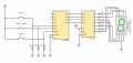
I don't understand. Aren't pins 1,2,6 and 7 inputs from the counter.
I have them connected to the CD4510 outputs. If I install pull-downs
it will short out the CD4510. I must be missing something.
Disconnect the CD4510 for now. We are testing the CD4511 only.
If you connect 1k-10kΩ pull-down resistors, you are inputting zero. We ought to see "0" on the display
After doing that, connect pin-7 to +5V. We ought to see "1" on the display.
(You can leave the pull-down resistors in place. They would not hurt anything.)
 

Thread Starter

maker_2023

Joined Nov 20, 2023
199
Disconnect the CD4510 for now. We are testing the CD4511 only.
If you connect 1k-10kΩ pull-down resistors, you are inputting zero. We ought to see "0" on the display
After doing that, connect pin-7 to +5V. We ought to see "1" on the display.
(You can leave the pull-down resistors in place. They would not hurt anything.)
OK. "0" test and the "1" test worked. My next step will be to get this beast counting.
 

Thread Starter

maker_2023

Joined Nov 20, 2023
199
Did that. It now displays a "6" and doesn't count.
It is now counting down. The problem was that I had a single LED
on the clock output so that I could see that the clock was working.
That must have killed the signal going to the CD4510?

The funny thing is, if I power down and back up, the count starts at weird values, not
"0".
 
Last edited:

MrChips

Joined Oct 2, 2009
34,974
It is now counting down. The problem was that I had a single LED
on the clock output so that I could see that the clock was working.
That must have killed the signal going to the CD4510?

The funny thing is, if I power down and back up, the count starts at weird values, not
"0".
All newcomer mistakes.

1) When you power up, the counter will start at any random state. We can fix that later.
2) Never connect LEDs directly to logic signals. Always use an inverter or buffer to drive the LED. Never assume that the signal that drives the LED is a valid logic voltage. In other words, don't take that signal to drive another logic circuit.

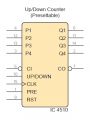
Now, remove the GND at pin-10 of the CD4510.
Connect pin-10 to +5V and watch the counter count UP.
 

Thread Starter

maker_2023

Joined Nov 20, 2023
199
All newcomer mistakes.

1) When you power up, the counter will start at any random state. We can fix that later.
2) Never connect LEDs directly to logic signals. Always use an inverter or buffer to drive the LED. Never assume that the signal that drives the LED is a valid logic voltage. In other words, don't take that signal to drive another logic circuit.

Now, remove the GND at pin-10 of the CD4510.
Connect pin-10 to +5V and watch the counter count UP.
Thanks for the inverter/buffer advice. I will put that in my notes.
The circuit now counts up.
M
 

dl324

Joined Mar 30, 2015
18,432
The problem was that I had a single LED
on the clock output so that I could see that the clock was working.
That must have killed the signal going to the CD4510?
You don't mention what is generating the clock or what the forward voltage of the LED is.

If you take the time to read the datasheets, they'll give you the information you need.

From the TI datasheet:
1707176891223.png
1707176918624.png
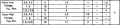
The counter increments on the rising edge of the clock. With a 5V supply, a high level input voltage must be at least 3.5V.

If you were using a red, green, or yellow LED, the forward voltage is probably less than 3.5V.

Input signals greater than 1.5V but less than 3.5V will give unpredictable results.
 

MrChips

Joined Oct 2, 2009
34,974
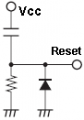
Now, about that POWER-ON RESET (POR) circuit.
You can get fancy or you can go simple

Firstly, you need to know if it takes a logic HIGH or logic LOW signal to RESET.
Read the device datasheet.

CD4510 datasheet

CD4510 requires high voltage to RESET.
So we want a high voltage that falls to low voltage after a short delay.

Here is your simple logic HIGH reset.
Try,
R = 100kΩ
C= 0.1μF to 1μF
Add a diode to speed up the discharge of the capacitor on POWER DOWN.

1707178362363.png
 

Thread Starter

maker_2023

Joined Nov 20, 2023
199
Now, about that POWER-ON RESET (POR) circuit.
You can get fancy or you can go simple

Firstly, you need to know if it takes a logic HIGH or logic LOW signal to RESET.
Read the device datasheet.

CD4510 datasheet

CD4510 requires high voltage to RESET.
So we want a high voltage that falls to low voltage after a short delay.

Here is your simple logic HIGH reset.
Try,
R = 100kΩ
C= 0.1μF to 1μF
Add a diode to speed up the discharge of the capacitor on POWER DOWN.

View attachment 314548
Thanks!
 
Top