Hi maker,
Try using a series resistor on the CD4033 output to the LED of half its present value.
Check the brightness, and any signs of the CD4033 overheating
E
Hi maker,
Try using a series resistor on the Common LED to 0V, of half its present value.
Check the brightness, and any signs of the CD4033 overheating
E
You are using common cathode 7-segment LED display.
Connect the common cathode to GND.
Feed one segment (anode) from 5V via a series resistor. Adjust the value of the resistor for suitable brightness. Don't go below 100Ω.
Measure the voltage across the resistor. Measure the resistance value (while out of circuit).
After that, we will be able to suggest a suitable display decoder/driver.
Edit: If you have CD4511, use those as decoder/driver. Use a separate BCD counter.
You are using common cathode 7-segment LED display.
Connect the common cathode to GND.
Feed one segment (anode) from 5V via a series resistor. Adjust the value of the resistor for suitable brightness. Don't go below 100Ω.
Measure the voltage across the resistor. Measure the resistance value (while out of circuit).
After that, we will be able to suggest a suitable display decoder/driver.
Edit: If you have CD4511, use those as decoder/driver. Use a separate BCD counter.
Hi MrChips:
I found that the 220 ohm resistors allowed for suitable brightness with +5V supply but
no value of resistor seems to work well in the actual counter circuit.
I have 4510s and 4511s. I will try them.
Thanks,
M
Hi MrChips:
I found that the 220 ohm resistors allowed for suitable brightness with +5V supply but
no value of resistor seems to work well in the actual counter circuit.
I have 4510s and 4511s. I will try them.
Thanks,
M
The data I posted in post #11 indicates the device can source about a quarter mA at Vo=4.5V. You could get more by loading the output, but that's an iffy call.
Try the display with the CD4511 decoder/driver.
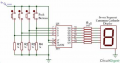
Connect the common cathode to GND. Connect the segments via a 220Ω resistor to the output pins of the CD4511.
Ignore the push-buttons for now. Just connect LT (pin-3) to GND. All the segments should light up showing the numeral 8.
Try the display with the CD4511 decoder/driver.
Connect the common cathode to GND. Connect the segments via a 220Ω resistor to the output pins of the CD4511.
Ignore the push-buttons for now. Just connect LT (pin-3) to GND. All the segments should light up showing the numeral 8.
What you've shown looks correct, but you have important inputs not shown.
BTW, schematic editors like Eagle don't usually include power connections for symbols. They're assumed (as is supply decoupling) to avoid cluttering the schematic. Every once in a while, some member will harp on missing power connections. They only need to be shown when they're significant in understanding circuit function.
What you've shown looks correct, but you have important inputs not shown.
BTW, schematic editors like Eagle don't usually include power connections for symbols. They're assumed (as is supply decoupling) to avoid cluttering the schematic. Every once in a while, some member will harp on missing power connections. They only need to be shown when they're significant in understanding circuit function.
I have now tried the circuit and it doesn't work. I have tested the clock portion of the circuit and it works. I tested the CD4511BE and the
Display prior to building the circuit and they work. I am wondering about the inputs.

 Facebook
 Google
 GitHub
 Linkedin