CD4033 Connections For 0 To 9 Counter

Thread Starter

maker_2023

Joined Nov 20, 2023
199
Hi:

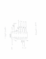
I have breadboarded a 0 to 9 counter using the CD4033. It doesn't work. I have confirmed
that the connections are as shown in the attached schematic. Can someone please tell me
if this is correct as I have seen several conflicting schematics.

Also, I saw somewhere that the CD4033 cannot drive even small 7-segment displays. Is that
true? If so, What would a driver circuit look like? The datasheet is rather confusing to a newbie.
The displays are common cathode 7.6mm in size but I have no further specs on them.

Thanks,
M
 

Attachments

Last edited:

dl324

Joined Mar 30, 2015
18,386
Is this schoolwork?

Post a schematic for those of us who don't care to use LTspice.

Also, I saw somewhere that the CD4033 cannot drive even small 7-segment displays. Is that
true? If so, What would a driver circuit look like?
From RCA datasheet:
1707004990552.png
 

Ian0

Joined Aug 7, 2020
13,158
Also, I saw somewhere that the CD4033 cannot drive even small 7-segment displays. Is that
true?
A long time ago it was almost true. 4000 series CMOS has a fairly limited output current, and when 7-segment displays needed 20mA they could get perhaps 5mA, so they would be rather dim.
Now 5mA is plenty of current for a 7-segment display as LEDs have improved, and 1mA should do for the high-brightness types.

If nothing is lighting up, make sure you have a common cathode display and that the cathode is connected to the negative supply.
 

Thread Starter

maker_2023

Joined Nov 20, 2023
199
Is this schoolwork?

Post a schematic for those of us who don't care to use LTspice.


From RCA datasheet:
View attachment 314332
Hi Dennis:

I am many decades past "homework"!

Thanks,
E
A long time ago it was almost true. 4000 series CMOS has a fairly limited output current, and when 7-segment displays needed 20mA they could get perhaps 5mA, so they would be rather dim.
Now 5mA is plenty of current for a 7-segment display as LEDs have improved, and 1mA should do for the high-brightness types.

If nothing is lighting up, make sure you have a common cathode display and that the cathode is connected to the negative supply.
Hi Ian:

Definitely common cathode. I thought that perhaps I misunderstood the data sheet wiring instructions.

M.
 

Thread Starter

maker_2023

Joined Nov 20, 2023
199
Hi maker,
Where did you get your CD4033 LTSpice model.

E
Hi E:
I got it from Bordodynov. I am not simulating the circuit. I just used the Spice
model to illustrate how I connected the device. I actually have no schematic as
I just wired it up based on various multi-digit counter circuits that I found on
the internet. I am going to draw a schematic and post it shortly.
M
 
Last edited:

dl324

Joined Mar 30, 2015
18,386
Schematic
1707066081580.png
1707066101555.png
As you mentioned earlier, the counter can't drive displays directly. For a common cathode display, you'll the emitter follower driver shown in the datasheet. The datasheet references an integrated transistor array, but you can use any general purpose NPN transistor.

To verify whether or not the counter is working, disconnect the display and measure the voltage on the segment outputs.

Schematics are easier to read if the symbols have inputs primarily on the left and outputs on the right to facilitate the preferred left-to-right flow, and pin function is shown:
1707066635734.png
 

Thread Starter

maker_2023

Joined Nov 20, 2023
199
View attachment 314358
View attachment 314360
As you mentioned earlier, the counter can't drive displays directly. For a common cathode display, you'll the emitter follower driver shown in the datasheet. The datasheet references an integrated transistor array, but you can use any general purpose NPN transistor.

To verify whether or not the counter is working, disconnect the display and measure the voltage on the segment outputs.

Schematics are easier to read if the symbols have inputs primarily on the left and outputs on the right to facilitate the preferred left-to-right flow, and pin function is shown:
View attachment 314361
That's a good idea to have inputs on the left and outputs on the right. Thanks.
This also means that every schematic on the internet is incorrect.
Do I need to put a driver transistor on each segment meaning 7 drivers per digit
or does the driver on connect to the 2 cathode pins?

M
 

dl324

Joined Mar 30, 2015
18,386
This also means that every schematic on the internet is incorrect.
I wouldn't say every schematic is in that style. The ones that don't conform were drawn by people who didn't know what they were doing. If you see more using pin order style, ignore them. They were likely drawn by novices.
Do I need to put a driver transistor on each segment meaning 7 drivers per digit
or does the driver on connect to the 2 cathode pins?
7 drivers per digit.

There are parts that can drive displays directly, but it'll take 2 chips.
 

Thread Starter

maker_2023

Joined Nov 20, 2023
199
I wouldn't say every schematic is in that style. The ones that don't conform were drawn by people who didn't know what they were doing. If you see more using pin order style, ignore them. They were likely drawn by novices.
7 drivers per digit.

There are parts that can drive displays directly, but it'll take 2 chips.
Oh man. Well that isn't going to happen. I have some CD4510s and CD4511s is a driver
necessary for those? If I would have to use two chips per digit anyway.
 
Last edited:

ericgibbs

Joined Jan 29, 2010
21,464
hi maker,
The earlier CD4033 source/sink currents are for the Old 'A' version.

The version 'B' which was released many years ago has much higher output currents, and should drive a modern
LED.
E
EG57_ 1455.png
 

sarahMCML

Joined May 11, 2019
699
I have the counter working now but the digits are so dim that they are
hard to read. I guess that I need drivers. Perhaps LCD displays would work better.
You could try finding UDN2981 or UDN2982's. Mouser still had some the last time I looked, although they're not cheap!
 
Top