Paralleling: Lets say there are four supplies. 36.0V, 36.1V, 36.2V, 36.3V. If the load is light and can be lifted by one supply the 36.3V one will be supplying the load. If the load is over what one supply can do, then it will be at 36.2V and one supply will be at current limit.
Option, Build one supply like normal. Build the next three with the input to the error amplifier at ground. This will cause the error amplifier to lift as high as it can. (almost any PWM but not the TL494) Most error amplifiers pull down strong but lift up poorly. Now wire all four error amp output pins together. Now all four PWM will run at the same current level. (same current if a current mode like the 3842 or same duty cycle like the voltage mode PWMs) This is common practice.
Thank you for your answer and recommendations. I will look up into the concept. But i did not understand that this method controls the output current, not the pwm signal's current ratings, right?
Current mode; A clock turns on the MOSFET. Current ramps up in the transistor. (current is monitor) When the current reaches a set point the MOSFET is turned off. The error amplifier controls the turn off point.
Voltage mode; The current is not looked at. A clock turns on the MOSFET. It is turned off in some uSseconds later. The error amplifier controls how many uS.
In all PWM the error amplifier looks at the output voltage and adjusts something to get the desired output voltage.
Look at the case of the voltage is a small amount too low. In current mode the error knows it is now pushing 1A to the load but it need to move up to 1.1A. In voltage mode it is set to 50% now but must move to 51%.
Thank you for your comment. I understood the concept, and it is a nice to know practice for parallel converters. I will go for the current mode with UC3843, if i decide to make the design with more then one boost converter.
Thank you. I am a little bit undecided that whether i want to use low current commercial inductors with parallel converters or i want to design an inductor and wind it for only one converter circuit. Turns, ferrit measurements, wire gauges etc. are okay but i am not sure how can i achieve a good current accuracy, precision and stability.
Both... each supply will see the averaged joint-voltage and will adjust its output accordingly. If one is a higher voltage than the other due to transmission losses then it supplies more current which will cause its output to drop and other supplies will take up the load. Ideally the feedback sense input for all PSU will be tied to the same location at the load...
I want to bring up this situation to you too Mr. Irving. If i design and wind up a new inductor i can raise inductance values around 100 µH - 200 µH and switching frequency will be lower, so ripple will be lower right? What are your toughts about winding a new inductor vs lower current inductors with parallel converters? I am soo undecided right now
I want to bring up this situation to you too Mr. Irving. If i design and wind up a new inductor i can raise inductance values around 100 µH - 200 µH and switching frequency will be lower, so ripple will be lower right? What are your toughts about winding a new inductor vs lower current inductors with parallel converters? I am soo undecided right now
No, ripple is worse if you lower frequency and increase inductance... Here,V(out) is 50uS/15uH v V(out2) at 5uS/1.5uH for the same output capacitor. To reduce the ripple on the lower speed version you need to increase C to 2000uF which makes settling time 30mS+
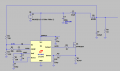
If you start out with the 12V being applied link in #69 the L will ring. I ramped the supply up slowly in 0.7mS and no ring over shoot. The over shoot you see if because I did not fix the error amp yet. (plot of Vin and Vout)
Thank you both for your answers. If i decide to wind a new inductor i wont raise the inductance. But how can i achieve a good current accuracy? Are wire gauge specifications enough?
A different MOSFET won't change things.. in my simulaton you can see its ON-time is 3.5uS in 5uS, 70% duty cycle. If the controller is limited to 50% then you're scuppered.
A different MOSFET won't change things.. in my simulaton you can see its ON-time is 3.5uS in 5uS, 70% duty cycle. If the controller is limited to 50% then you're scuppered.
Duty cycle = 1-(Input/Output) plus a little bit to allow for diode voltage drops etc.
so 1-12/36 = 66.6% plus a little bit more.
My guess at 75% might have been a bit too high, but it is still more than the UC3845 can manage.
One has to consider the spectrum of the inductor current. The majority of it is DC, for which the skin effect does not apply.
If the inductor is too small, the current spectrum will contain rather more at the switching frequency and its harmonics, and litz wire and a ferrite core will be necessary.
If the inductance is larger the ripple is lower, and an iron powder core wound with thick wire will be more suitable.
Too much Inductance and Capacitance is virtually always better than not enough.
Let a Transformer manufacturer specify a Choke for You using their special Software.
Don't try to "Wind-it-Yourself", You have no idea of what You will get when you're done,
and this is not a an insignificant amount of Power that is being converted.
At this point, I'm leaning towards a Push-Pull-PWM Transformer Output.
Much more stable and predictable.
.
.
.
If the L/R time constant is >> the switching time then the current through the inductor rises and falls almost linearly, as you can see below. The top trace is a 3.3uH inductor, the lower a 1.5uH inductor. A larger inductor produces less ripple current in the inductor (12.1A p-p v 26.6A p-p) but the DC (rms) component is virtually identical (63.7A v 64A) - for the same frequency. The duty cycle is only 0.3% different. The back-emf generated - ie the boost - is given by:
\(V_{bemf} = -L.δI/δt\)
where δt is the OFF time. So doubling the inductor for a given δt must halve the ripple. Alternatively, doubling the inductor and δt, so halving the frequency, generates the same ripple.
Have a go with the Micrometals software if you want to wind your own output inductor. http://www.iec-international.com/micrometals/micrometals/software.html
I'd thoroughly recommend the old DOS version over the new on-line version.
The old version gives you a choice of about half a dozen designs. The new one gives you 10,000!
A note on @Irving 's post #79
The higher the ripple current the greater the CORE loss in the output inductor. It varies as the peak-to-peak ripple current raised to the power 5/2.
The higher the inductance, the greater the COPPER loss in the output inductor. You can work out the copper loss from the length of wire and its thickness.
Iron powder inductors give more CORE loss than ferrite for the same peak-to-peak ripple current, but they will take more current than ferrite before saturation for a similarly sized core.
 Facebook
 Google
 GitHub
 Linkedin

")


