 Facebook
 Google
 GitHub
 Linkedin
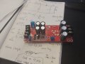
Thank you for your answer. But i am currently switching to UC3843, which is designed properly for buck boost converter circuits, thanks to Ian0's recommendations.The "10k pull down resistor" could be replaced with a active pull down circuit. I could change R8, 5 with 10 ohms.
View attachment 245448
Buck-Boost Converter Mosfet Problem
- Thread starter Oğuzhan Demir
- Start date
") . The information about device properties that i am not authorized to share, i am so sorry. But if we talk about reality circuit will not run even 2 hours a day. The max is 4 hours a day but i will not recommend it since from your numbers it is the limit.
. The information about device properties that i am not authorized to share, i am so sorry. But if we talk about reality circuit will not run even 2 hours a day. The max is 4 hours a day but i will not recommend it since from your numbers it is the limit.


