Buck-Boost Converter Mosfet Problem

Thread Starter

Oğuzhan Demir

Joined Aug 12, 2021
34
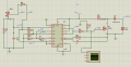
Hi, i designed a buck boost converter for 12v-60A input and 36V 20A output with 200kHz switching frequency and variable duty cycle with a desired effiency of 90%. With respect to my calculations i need 1,77 uH inductor and 183 uF capacitor with 200kHz switching frequency in order to complete the circuit. I used 1,5 uH inductor (in the picture there are 2 inductors parallel but i tried the circuit with 1 inductor) and 200 uF capacitor. When i start the power supply with 12V 1A limits, power supply gives 1A constantly and the mosfet acts like short circuit because of the inductor and heats up too much, and i only get 19V output. I don't know where i did wrong and any help is much appreciated.buck-boost.pngsignal.png
 

Ian0

Joined Aug 7, 2020
9,847
How long is 9130pF of gate capacitance going to take to discharge through at 10k resistor? I’d say about 180μs, and you want to run it at 5μs per cycle.
With a MOSFET that large, you really need a proper MOSFET gate driver.
 

Irving

Joined Jan 30, 2016
3,897
I don't know what drawing tool you used but its almost impossible to follow your schematic. It would be much easier to help you if you drew your schematic in KiCAD or signed up with EasyEDA, both of which are free.
 

LowQCab

Joined Nov 6, 2012
4,078
I would guess that You chose 200khz to take advantage of smaller Filter Components.
Now You are finding out that it's not that easy.
For Frequencies like that, You will need a properly sized, dedicated Gate-Driver.
I wouldn't try to go higher than ~50khz,
which will require much larger Filter Components.
Get one of the Transformer manufacturers to recommend a Choke for You.
They have very sophisticated software that will do the calculations perfectly,
that is, if You supply them with accurate information.

Also, You can't just substitute what ever parts You have in your junk-drawer,
You will need brand-new, over-spec Parts, manufactured by a reputable company.
.
.
.
 

Irving

Joined Jan 30, 2016
3,897
How long is 9130pF of gate capacitance going to take to discharge through at 10k resistor? I’d say about 180μs, and you want to run it at 5μs per cycle.
With a MOSFET that large, you really need a proper MOSFET gate driver.
You're right, this needs active drive in both directions. Also the emitter follower configuration is unlikely to get Vgs high enough to turn the MOSFET on fully.
 

DickCappels

Joined Aug 21, 2008
10,187
Even if you sketch the power stage by hand it would help a lot. My interpretation is that you have a boot converter when you need a buck
 

Irving

Joined Jan 30, 2016
3,897
Even if you sketch the power stage by hand it would help a lot. My interpretation is that you have a boot converter when you need a buck
He wanted to go from 12v to 36v so definitely a boost converter, the general configuration being...


1628767011980.png1628767139413.png


Which he has, albeit badly drawn...
 

LowQCab

Joined Nov 6, 2012
4,078
Also, there is no practical way to insure equal Current sharing between the 2-Diodes.
And, there's no telling what might really happen when trying to parallel Inductors.
.
.
.
 

Ian0

Joined Aug 7, 2020
9,847
Perhaps a slightly more modern control IC would be in order, such as a UC3843. (That’s the version with a UVLO that will allow it to run at 12V.) Then we will have moved from the swamps to the age of the dinosaurs, and have something which is actually designed to drive a MOSFET.
As this will need a duty cycle of 75%, perhaps something even more modern with easier-to-implement slope-compensation would be the device of choice.

with any switched-mode bigger does not necessarily mean better when it comes to MOSFETs. A large device will cause more switching losses, and a small one more conduction losses.
 

Thread Starter

Oğuzhan Demir

Joined Aug 12, 2021
34
How long is 9130pF of gate capacitance going to take to discharge through at 10k resistor? I’d say about 180μs, and you want to run it at 5μs per cycle.
With a MOSFET that large, you really need a proper MOSFET gate driver.
Thank you for your answer. I want to ask, can reducing the discharge resistor be an answer to the problem? Or is it impossible to reach 5µs discharge cycle without gate driver? And also does this conventional drive circuit solve my problem? Assuming Vcc is 12V and again pwm signal is genereted from TL494.
 

Attachments

Thread Starter

Oğuzhan Demir

Joined Aug 12, 2021
34
I don't know what drawing tool you used but its almost impossible to follow your schematic. It would be much easier to help you if you drew your schematic in KiCAD or signed up with EasyEDA, both of which are free.
Thank you for your answer. Sorry for the poor information in the pictures. I'm using Eagle for drawing and some of the components i choosed does not have cad files for eagle so i drew them too and neglected the informations because drawing was a personal drawing, i did not foresee that i would be posting it :) . The schematics is the exact schematics in your reply to DickCappels. Also the pwm signal part is a classic pwm signal generation circuit for TL494 with 200kHz and variable Duty Cycle, which works fine in my experiments. I think my main problem is mosfet with 200kHz frequency, thanks to this thread. Here is the pcb design that i tried to run, maybe it helps.
 

Attachments

Thread Starter

Oğuzhan Demir

Joined Aug 12, 2021
34
I would guess that You chose 200khz to take advantage of smaller Filter Components.
Now You are finding out that it's not that easy.
For Frequencies like that, You will need a properly sized, dedicated Gate-Driver.
I wouldn't try to go higher than ~50khz,
which will require much larger Filter Components.
Get one of the Transformer manufacturers to recommend a Choke for You.
They have very sophisticated software that will do the calculations perfectly,
that is, if You supply them with accurate information.

Also, You can't just substitute what ever parts You have in your junk-drawer,
You will need brand-new, over-spec Parts, manufactured by a reputable company.
.
.
.
Thank you for your answer. You are right, the purpose of 200kHz to use small values of inductance and again you are right this is hard :) . But i really need to be cost-efficient, i am buying the products from digikey and i am from Turkey, and it takes too long time to buy products from abroad. So i am trying to be cost-efficient and the components must be easy to find-buy. I tried to stay between 20kHz-30kHz frequencies but pre-manufactured components made it hard to stay in the cost-efficient line.
inductor : SRP1265C-1R5M
 

Thread Starter

Oğuzhan Demir

Joined Aug 12, 2021
34
Perhaps a slightly more modern control IC would be in order, such as a UC3843. (That’s the version with a UVLO that will allow it to run at 12V.) Then we will have moved from the swamps to the age of the dinosaurs, and have something which is actually designed to drive a MOSFET.
As this will need a duty cycle of 75%, perhaps something even more modern with easier-to-implement slope-compensation would be the device of choice.

with any switched-mode bigger does not necessarily mean better when it comes to MOSFETs. A large device will cause more switching losses, and a small one more conduction losses.
Thank you for your answer, also thanks for the recommendation. UC3843 would be a good choice for the design, i will look into it. My design goal is to reach 36V and 20A output, also i understood that calculations work only in a perfect world, which is impossible. I used 1.5 µH 31A 2,8 mOhm inductor, should i change it in order to reach my goal?
 

Thread Starter

Oğuzhan Demir

Joined Aug 12, 2021
34
Even if you sketch the power stage by hand it would help a lot. My interpretation is that you have a boot converter when you need a buck
Thank you for your answer. Here is the schematics i drew quickly in Proteus. Inductor mosfet and diode is random choosen.
I used components as;
Inductor: SRP1265C-1R5M
Mosfet: STP110N8F6
Diode: SDT30B100D1-13
 

Attachments

Irving

Joined Jan 30, 2016
3,897
Thank you for your answer. I want to ask, can reducing the discharge resistor be an answer to the problem? Or is it impossible to reach 5µs discharge cycle without gate driver? And also does this conventional drive circuit solve my problem? Assuming Vcc is 12V and again pwm signal is genereted from TL494.
A simulation shows the difficulties to be addressed...
Inductor choice is critical... while average current is 60A, it must have a saturation current of >90A else regulation is going to be hard to achieve. Your chosen inductor is not going to cope. Also your MOSFET drain current peaks close to the limit for a TO220 package...

And you'll need to implement some form of soft start as otherwise things are going to go very wrong in the start-up phase....

All in all this is a highly marginal design...
1628772761773.png

Looking in more detail, your gate driver needs to handle +/- 3A gate current. An alternative MOSFET might help, but in view o my other comment above you might need to consider parallel MOSFETs

1628773996153.png
 

Irving

Joined Jan 30, 2016
3,897
Further to the simulation, your MOSFET losses are around 38W and so are your diode losses...

For this sort of output current you should really be considering:
  • Synchronous rectification;
  • Multiphase conversion;

Look at the VRM on a PC motherboard, ok they are buck not boost, but the output currents are 30A+ and to keep things small and cool they run 8, 10 or even 14 phases... essentially multiple 'parallel' converters. Its much easier to design a good 5A converter and have 4 or 5 of them in parallel...
 

Thread Starter

Oğuzhan Demir

Joined Aug 12, 2021
34
A simulation shows the difficulties to be addressed...
Inductor choice is critical... while average current is 60A, it must have a saturation current of >90A else regulation is going to be hard to achieve. Your chosen inductor is not going to cope. Also your MOSFET drain current peaks close to the limit for a TO220 package...

And you'll need to implement some form of soft start as otherwise things are going to go very wrong in the start-up phase....

All in all this is a highly marginal design...
View attachment 245443

Looking in more detail, your gate driver needs to handle +/- 3A gate current. An alternative MOSFET might help, but in view o my other comment above you might need to consider parallel MOSFETs

View attachment 245446

Thank you for your answer. I am very impressed that you did a simulation for the thread, thank you so much. Can you tell the simulation program's name so i can learn it? And, thank you for the recommandations for inductance and mosfets. I am learning that calculations are very small portion of the design marathon. Thanks for the tips for choosing components. Also in your simulation, input current peaks to 240A, i will be feeding the circuit with car batteries and 240A is not reachable for me. I want to ask, is it possible to add a PID circuit with operational amplifiers for current control with shunt resistors to reduce the peak and make input current more stable? Circuit will be like this and feedback will come from shunt resistor's voltage: Circuit-of-PID-Control.png

Also, i think my variable to control the current will be the switching frequency for this circuit, right?
 
Top