An LED Chaser based on a 555 and 4017.

Thread Starter

DanielLitwin

Joined Mar 23, 2017
52
I decided to use your ideas to cut down on components and make the chaser look more like the following gif (probably at 2.5-3x the frequency). There also doesn't necessarily need to be a pause in between loops. That was just put in there when I converted the mp4 to a gif.
 

Attachments

djsfantasi

Joined Apr 11, 2010
9,237
I decided to use your ideas to cut down on components and make the chaser look more like the following gif (probably at 2.5-3x the frequency). There also doesn't necessarily need to be a pause in between loops. That was just put in there when I converted the mp4 to a gif.
I like it! It's what I imagined that it would look like
 

Thread Starter

DanielLitwin

Joined Mar 23, 2017
52
Yeah, this will be much easier to design!

If I'm not mistaken; I'll only need 2 CD4017s pulsed by a 555; and for the outer ring I will need (18*n) led's for the chaser to be keep it in sync?
 
Last edited:

Bernard

Joined Aug 7, 2008
5,784
2- 4017's will give 17 outputs, see post # 5.
For outer ring, 18 LEDs will be fairly wide spaced, how about a multiple of 18, 36 or 54 ?
Any bells & whistles for the ring ?
 
Last edited:

Bernard

Joined Aug 7, 2008
5,784
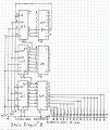
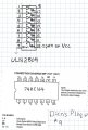
Another attempt to satisfy post # 81. Drivers included for all outputs of shift register 74HC164 as every third output
driving 5 LEDs would need a driver, other outputs drive 2 LEDs, one in square wave and one in bar.
First error, U4-3 should be driving a SB-( or is it BS?), maybe enough to get the picture. R1 to be determined
depending on LED color & current.
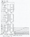
Clock can be 555. Not shown is start-up reset. Starting at reset, U1-1,2, serial input ( second error- 1 & 2 should go to + 6 V instead of ground. ) are tied high so on first clock a high is loaded into first stage, continuing until U6-16 goes high on 19th count, inverted now as clear signal, resetting all stages.Dan\'s Plaque # 6 00000.jpg .
 
Last edited:

Bernard

Joined Aug 7, 2008
5,784
Might be better to post on your project rather than in box as it was just a quirk that I peeked in today.
For ease of drawing I put pin numbers where ever they shorten lines. This is not a pin-out drawing of the ICs.
R 55 is a charge path for C 2. It might be difficult looking for the clear signal on a scope as it might be only nano sec. long, & we want to be sure that all stages are reset, so we stretch the pulse.
I ran out of paper to show the other 38 LEDs. Just repetition following the logo.
The clock is applied to the clock buss or at any pin 8 on SR.
 

Bernard

Joined Aug 7, 2008
5,784
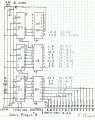
Does this help in assigning outputs to LEDs ?
" Why so many parts ", just 6 ICs, but if designed in China, there would be just one R / group of LEDs, not suggested by AAC.Dan\'s Plaque # 8 00000.jpg
 

Thread Starter

DanielLitwin

Joined Mar 23, 2017
52
haha very true, I've grown spoiled with how small and compact IC's have gotten--and yes, it definitely helps--just working on translating it into the pinouts of the registers/bjt arrays
 

Thread Starter

DanielLitwin

Joined Mar 23, 2017
52
Though, on your drawing of plaque 8 (and others), I was curious as to why you had an inverter on U6 going from 3 to 16? Maybe I'm having a brain fart.

EDIT*** I looked at the datasheet for the component; Bernard was drawing one of many inverters.
 
Last edited:

Bernard

Joined Aug 7, 2008
5,784
I just picked 1 of the 24 inverters to illustrate that we were inverting the output of U3-5 to provide a low
for the clear signal. The small circle at pin 9 of U3 indicates that a low is required to clear.
 

Thread Starter

DanielLitwin

Joined Mar 23, 2017
52
Yeah that makes sense to me now, I think the reason I'm having trouble is the connections between the registers and bjt arrays as the data sheets all show the labelled different. Also, On U1, U2, and U3, are the outputs seem to be what's throwing me off judging by the datasheets for both of the main components.

On the LEDs; do we really want the anode to ground? I was going to spin the LEDs around and skip the current limiting resistors; and place one at the bottom as I've seen done before with clock based signals where only one 'unit' will be on at a a time. Then, I would obviously separate the grounds so I didn't have a voltage drop ;)
 

Thread Starter

DanielLitwin

Joined Mar 23, 2017
52
This could be part of the problem--the footprints I've been working with don't mirror how you draw them. That should not matter, but I'm a visual learner so it complicates things. It seems as though your designators are upside down in comparison to the datasheet
 

Attachments

Last edited:

Bernard

Joined Aug 7, 2008
5,784
Dan's Plaque #8, note that LED anodes connect to SR serial inputs 1,2, & on to +6V.
" I was going to spin the LEDs---" Over my head.
" One unit on at a time ". Review picture on post #81 & note that when a LED is illuminated it remains on
until all 54 LEDs are on. With SR serial inputs tied hi, clock will put a hi into stage 1, second clock, hi advances
& a new high is loaded into stage 1. This keeps up until all 54 LEDs are lit. On 19th clock , U6-16, 3rd stage goes high, resetting ( clearing ) all stages.
On a 4017 chaser, a single current limiting resistor can be used as only one output is hi at a time.
 

Thread Starter

DanielLitwin

Joined Mar 23, 2017
52
Oh okay, having all of the outputs active as it chases until it reaches the reset works better. I was thinking I'd use the decade counter for the ring around the design (I was looking at a schematic that could accomplish that).

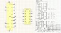
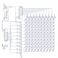
SIDE NOTE*** This may be a stupid question, but in the photo that I have included here, could someone tell me which way the LED's light up? I've seen versions that say that they go high horizontally; and then onto the next row, etc. I've also had people say that they will light up vertically (i.e., start at the top and work it's way down, then start at the top of the next column).

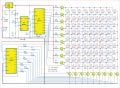
The same question applies for the the second image that has yellow schematic parts and only 81 LEDs vs 100.
 

Attachments

Last edited:

Bernard

Joined Aug 7, 2008
5,784
First chaser. Note that U2 advances one step for 10 of U1. At reset U2-0 is high, enabling the first vertical column. As U1 count advances, LEDs D1 is already on, D2 next, & so on until D10 turns on, advancing U2 one count & we start second column, D11 - D20.
Yellow print. Follow the clock, 555-3 to IC3 then to IC4. First vertical column enabled, LED1 on. First step, Q1 hi, LED10 on, & down to LED73.
There is no provision for reset at power-up.
 
Last edited:

Thread Starter

DanielLitwin

Joined Mar 23, 2017
52
I was thinking about using something like that for the outer ring; but obviously something with compacted packages (no need for individual 20 BJTs) and hook it up to the same clock
 

Bernard

Joined Aug 7, 2008
5,784
Keep in mind the laying out of a PCB, a matrix is compact but stretched out it becomes a can of worms.
Using SRs, the ICs can be kept close to The LEDs. If ring has 72 LEDs,( 9 SRs ), then its clock can be divided by 4
and used as the bar clock. Every thing stays in sync. Different patterns can be loaded, single circulating bit,
marque, inverted marque, or random pattern. I believe that you have seen the short videos of each.
 
Top