An LED Chaser based on a 555 and 4017.

Thread Starter

DanielLitwin

Joined Mar 23, 2017
52
I'm new here so forgive me if this is the wrong place to place this... I see this is an old thread but I'm hoping it notifies those "in the know." I'm trying to design a fun little bit of digital electronics for morale boost at my company. I recently built a small chaser and thought it would be cool to have one that' s more "company related."

It's basically two designs in one.
1. An LED Chaser based on a 555 and 4017 (may have to be casecaded which I'm not so sure about).
2. A "Throbbing" LED Chaser that runs on loop (as does #1)

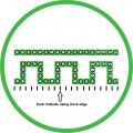
The idea is that Everything on the front face of this PCB is an LED (color will be decided later, as will the orientation and design of LEDs A-F (due to IP/Company policy :(...)

LEDS #1-16: (most likely more depending on the size of the PCB; lets assume it's 32)
  • They will chase from #1-16
  • They will throb (as I've seen previously in the thread) fading in their intensity.
  • This will in effect create a chasing circle that fades in/out while the LED is on (another option is having a follower so that the previous LED is on at half intensity)
LEDS A-F:
  • There will most likely be more than 6 LEDs, in fact there will be at least 14.
  • They will also chase in straight forward chase fashion using a 555 timer and 4017 decade counter.
  • This part I know how to do with relative confidence (except the possibility of cascading 4017's--or putting them in series, whatever the terminology is).
LEDS H, I, and J:
  • These LEDS will literally follow the exact chase of LEDs A-F (so if my current drive capability is high enough, I could simply put them in parallel as they will be on/off at the same time.
  • Here's the tricky part: I'd like the chase of LEDs 1-16's revolution to end at the same time as the LEDs A-J finish their routine (a simple routine at that). I would like to do this without adding a PIC; I would like to do this with nothing but digital chips.
If anyone can help, please let me know, I know my circuits are vague, but this isn't a school assignment or anything--where I work I'm more used to working with analog/power electronics.

Thanks!
Dan


Moderator's Note:
Please don't hijack other member's thread, now you have your own.
This thread was split from --
LEDs, 555s, Flashers, and Light Chasers.
https://forum.allaboutcircuits.com/...s-and-light-chasers.19075/page-4#post-1111966
 

Attachments

Bernard

Joined Aug 7, 2008
5,784
You really should have your own post.
It is all doable, but you need to decide on number of LEDs. It would be best if lettered group
is a sub multiple of outer ring, ie outer ring would be a multiple of A- F, 6 X 2, 3,or 4. For A-L there are 8 clocked stages giving outer ring 16 or 32: A-T, 15 X 2 for 30.
Dropping brightness of trailing LED is easy in simplest case but adds a lot of parts. Can also simulate comet tail with even more parts.
How bright do LEDs need to be. With 8 V supply ( loaded 9 V battery ? ) a 4017 can output up to 10 mA.

l
 
Last edited:

Thread Starter

DanielLitwin

Joined Mar 23, 2017
52
Sorry about hi-jacking a thread, I didn't exactly know where it belonged, except I saw a plethora of examples that seemed to fit what I was trying to do so thank you for making it it's own post. I will be working with any voltage of my choosing. The mains input will be roughly 350VDC (we deal in high voltage) which will be stepped down via a CUI converter (something like what we used to step down to run our uC, LDOs, sensors, etc); so I could run off of 5V, 12V, 15V, etc. all at multiple output current capabilities, so power isn't an issue. Number of components also isn't an issue and neither is board size. Since we own the patent on the logo, I guess I shouldn't be so worried about keeping the general shape of the LED makeup a secret. If it is okay, I can privately message you the exact logo that I'm trying to replicate in LEDs.
 

Thread Starter

DanielLitwin

Joined Mar 23, 2017
52
Here's a more detailed explanation of what I mean. The black lines indicate rising clock edges. I would ideally separate the bottom "snake" looking logo from the above solid green bar. However, I'd like the LED's from the "snake" to light up in order; a→b→c→d→e→f, etc. However, at the same time, with regards to the green bar above the "snake" part of the logo, I'd like the LED B to stay light while LED B, C, D and E on the square wave light up. So on, so forth. So imagine a square wave lighting up one by one; while the bar above also lights up one at a time (though when one of the vertical sections of the square wave lights up, the LED on the bar above stays lit--I would imagine this would make it tied to four of the outputs on a counter or something of the like.

As for the green circle on the outside; I planned for that to slowly chase clockwise until they're all on--then reset.

Is this possible with 555's, 4017s and BJTs? I've made LED chasers before but that was with one 4017--I've never had to cascade them before. Also, as I mentioned, my specialty is in analog electronics and high voltage electronics so I'm still learning digital logic.

Any help would be phenomenal--even to be pointed in the right direction.

Thanks
-Dan
 

Attachments

crutschow

Joined Mar 14, 2008
38,503
This diagram in the CD4017 data sheet shows to cascade them:
upload_2017-3-25_21-43-43.png

You said A-F will be at least 14 LEDs.
So why not make them 16 LEDs like group 1-16?
 

Dodgydave

Joined Jun 22, 2012
11,395
So you have two separate patterns, leds 1-32, and leds A-J(10 leds) and they need to finish at the same time with fade on the A-J leds, similar to the Knightrider effect?
 
Last edited:

Bernard

Joined Aug 7, 2008
5,784
Outer ring is like a bar graph, each LED stays on when triggered ?
Snake is conventional chaser, only one LED on at a time ?
What is relation of ring clock to snake clock ?
 

Thread Starter

DanielLitwin

Joined Mar 23, 2017
52
Outer ring is like a bar graph, each LED stays on when triggered ?
Snake is conventional chaser, only one LED on at a time ?
What is relation of ring clock to snake clock ?
Without revealing too much of the tra
So you have two separate patterns, leds 1-32, and leds A-J(10 leds) and they need to finish at the same time with fade on the A-J leds, similar to the Knightrider effect?
Technically yes, there are two separate patterns. There is the outer ring. This will start at 12:00 (if it were a clock face). The number of LEDs in the outer ring has yet to be determined, but the first led will light up on the first rising edge; and on the second rising edge, the second LED will let up (while the first one stays on). This all continues until the entire ring is lit up; and then the loop repeats itself.

For a little background, This is our company's patented logo. Our company makes what we call "Digital Electricity." So the interior part of the logo is the combination of the the symbols of an AC waveform and a DC waveform. The outer ring is just a border for our product (that we also put on Tshirts and stickers and the like.

The relationship between the outer ring and the inner design is that they finish at the same time (because in my opinion it would look cleaner that way; as opposed to having the 'winshield wiper' effect where it gets out of sync.
 

Thread Starter

DanielLitwin

Joined Mar 23, 2017
52
So you have two separate patterns, leds 1-32, and leds A-J(10 leds) and they need to finish at the same time with fade on the A-J leds, similar to the Knightrider effect?

I updated the image in my post last night at 9:29PM so that it made more sense-after making sure that the image was entirely patented. Board space, component count, power source, and cost aren't really an issue. I've decided to make these as a gift to the team of engineers that have worked on our main projects with me.
 

Thread Starter

DanielLitwin

Joined Mar 23, 2017
52
This diagram in the CD4017 data sheet shows to cascade them:
View attachment 123393

You said A-F will be at least 14 LEDs.
So why not make them 16 LEDs like group 1-16?
I'm
This diagram in the CD4017 data sheet shows to cascade them:
View attachment 123393

You said A-F will be at least 14 LEDs.
So why not make them 16 LEDs like group 1-16?

That cascaded schematic is quite helpful, thank you!

The first image I posted was very crude, so in the future I'll be referring to the second image I posted (with Green and White coloring, not Black and White).

As for A-F being 14 LEDs, my count is 9. Looking at the most recent image I posted that clarified my hopes in the design, I would like LED_A in the square wave to light up at the same time as LED_A in the bar above it (and stay on). Then LED_B would turn on within the square wave (as would LED B in the DC Bar above). These would both stay on. Next, while LED_B in the above Bar is still on, LED C will illuminate and stay on (not changing the state of LED_B in the above bar). Followed by this, LED_D would illuminate and stay on while LED_B remains on. Lastly, LED_E turns on (and stays on) while LED_B continues to have its forward voltage satisfied.

At this point, LEDs A, B, C, D, and E are all on (and STAY on).

From this point, LED G turns on and stays on; then LED H turns on and stays on (on both the square wave and the above-bar). While LED H and all the LEDs before it are still on, the LEDs I, J and K illuminate one by one, and the cycle continues.

Thank you!
 

dl324

Joined Mar 30, 2015
18,326
As for A-F being 14 LEDs, my count is 9. Looking at the most recent image I posted that clarified my hopes in the design, I would like LED_A in the square wave to light up at the same time as LED_A in the bar above it (and stay on). Then LED_B would turn on within the square wave (as would LED B in the DC Bar above). These would both stay on. Next, while LED_B in the above Bar is still on, LED C will illuminate and stay on (not changing the state of LED_B in the above bar). Followed by this, LED_D would illuminate and stay on while LED_B remains on. Lastly, LED_E turns on (and stays on) while LED_B continues to have its forward voltage satisfied.
Something like this?
 

Thread Starter

DanielLitwin

Joined Mar 23, 2017
52
This diagram in the CD4017 data sheet shows to cascade them:
View attachment 123393

You said A-F will be at least 14 LEDs.
So why not make them 16 LEDs like group 1-16?
Actually, this schematic of cascading decade timers is incredibly helpful. I've included an updated image of what my intentions are:

I just realized that this is very hard to describe with such little visual aid, so I've provided a timing diagram to make it a little more understandable. Maybe this will help to relay what I'm trying to achieve; my apologies for being vague. As far as the timing diagram goes, ignore the outer ring for now; this is strictly about the "snake" waveform. I figure from now on when we refer to the timing of the LEDs, we can use these two files as they seem to make the most sense to me.

Thank you!
Best,
Dan
 

Attachments

Bernard

Joined Aug 7, 2008
5,784
How bright ? Might test a few LEDs to see how they look.
For making long bar graphs, ring & snake, parallel output shift registers work well, easy to cascade.
For a sample, look at YouTube, Jack Bernard river ; input is a candle LED.
Also is 74HC154 & 4 bit counter for 16 active low, 8 mA outputs. Easy to cascade.
On drawing, snake has 36 LEDs, if ring also had 36 LEDs, would just need one SR or 4017's for both.
Bar would be driven by snake via ORs or neg. NANDs.
Need to know if LED drivers will be required.

.
 

Thread Starter

DanielLitwin

Joined Mar 23, 2017
52
Something like this?
This is something they could also work. Do you have a BOM for this circuit?

Tackling the outer ring will be another battle, I imagine it will be a led chaser with some kind of sample and hold feature where the frequency of the square wave chaser sychronizes with outer ring LED chaser. Such that alll leds (# undetermined) light up one at a time (and stay on) until the last LED lights up and the entire cycle resets.


Thanks for posting the schematic!
Dan
 

Thread Starter

DanielLitwin

Joined Mar 23, 2017
52
I should also notice that while this is the effect I am looking for, I would like the LEDs to light up in that exact order, except they stay on until the cycle resets (which is what I plan on doing with the outer ring).

-Dan
 

Bernard

Joined Aug 7, 2008
5,784
Here is an example of how make a bar graph from a 4017; redrawn by Wendy from my original sketch.BAR Graph # 2 00000.jpg
The batch of ORs are not needed with shift register option
 
Top