RGB LED chaser, PIC based, improvement from cd4017 circuit

Thread Starter

takao21203

Joined Apr 28, 2012
3,702
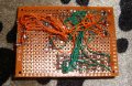
I've assembled the prototype now, using a 16F716 I have some of these around from a few years ago.

Circuit is a matrix, common Anodes which are driven by PORTB, and cathodes for each color also connected , sink is done with 2n7002 mosfets.

It is programable fully, compared to these CD4017 circuit kits, which are surprisingly popular but a bit boring after some time.

Subject of examination are how much voltage does this display need,and how many bits resolution i get for each component R,G,B (using a 5 MHz resonator, this PIC needs less than 1mA for itself).
And of course, how does it actually looks like?
 

Attachments

pwdixon

Joined Oct 11, 2012
488
Need to see a schematic really but are there any LED resistors?
Also, can you explain what your question is as it's not dreadfully clear?
 

Thread Starter

takao21203

Joined Apr 28, 2012
3,702
Need to see a schematic really but are there any LED resistors?
Also, can you explain what your question is as it's not dreadfully clear?
this just to documentate for myself and to publish for the consideration of others.

Resistors arent needed. i plan to add mcp1640 to run from single battery
 

pwdixon

Joined Oct 11, 2012
488
The I/O port is not the issue as the FET is taking the LED load current, you may well be getting away with this as the LEDs are not permanently illuminated (until you get a software fault) and the battery resistance is dropping the battery volts to the level of the LED forward voltage.
 

Thread Starter

takao21203

Joined Apr 28, 2012
3,702
The I/O port is not the issue as the FET is taking the LED load current, you may well be getting away with this as the LEDs are not permanently illuminated (until you get a software fault) and the battery resistance is dropping the battery volts to the level of the LED forward voltage.
no it also works from 5v when the multiplex is off.
Powering by the pickit3.
Thats not the point here its just a technique used.

I got it working today so far, the LEDs cycle through, and change colors.
Different to a CD4017, here the LEDs cycle back and forth.

Code:
/******************************************************************************/
/* Files to Include                                                           */
/******************************************************************************/

#if defined(__XC)
    #include <xc.h>         /* XC8 General Include File */
#elif defined(HI_TECH_C)
    #include <htc.h>        /* HiTech General Include File */
#endif

#include <stdint.h>        /* For uint8_t definition */
#include <stdbool.h>       /* For true/false definition */

#include "system.h"        /* System funct/params, like osc/peripheral config */
#include "user.h"          /* User funct/params, such as InitApp */

/******************************************************************************/
/* User Global Variable Declaration                                           */
/******************************************************************************/

/* i.e. uint8_t <variable_name>; */
const unsigned char phase_patt[]={1,2,4};

const unsigned char animtbl1[]={0,0,1,2,4,8,16,32,64,128,0,0,128,64,32,16,8,4,2,1};
unsigned char animsteps=sizeof(animtbl1);

const unsigned char allred[]={0xf,0xf,0xf,0xf,0xf,0xf,0xf,0xf,\
                              0x0,0x0,0x0,0x0,0x0,0x0,0x0,0x0,\
                              0x0,0x0,0x0,0x0,0x0,0x0,0x0,0x0};

const unsigned char allgreen[]={0x0,0x0,0x0,0x0,0x0,0x0,0x0,0x0,\
                           0xf,0xf,0xf,0xf,0xf,0xf,0xf,0xf,\
                           0x0,0x0,0x0,0x0,0x0,0x0,0x0,0x0};

const unsigned char allblue[]={0x0,0x0,0x0,0x0,0x0,0x0,0x0,0x0,\
                               0x0,0x0,0x0,0x0,0x0,0x0,0x0,0x0,\
                               0xf,0xf,0xf,0xf,0xf,0xf,0xf,0xf,0xf};

unsigned char flags,porta_buf;

unsigned char rgbleds[32];

unsigned char phase,refresh_ctr,disp,i;
unsigned char output_buf,shl_val;
unsigned char color_ctr,blink_ctr;

unsigned char mask_outputbuf,animidx,moving_ctr;

void init_leds(unsigned char*s)
{unsigned char i;
 for(i=0;i<24;i++)
 {
  rgbleds[i]=*(s+i);
 }
}

void copyleds_phase()
{unsigned char disp,i;
    disp=phase<<3;
 for(i=0;i<8;i++)
 {
  rgbleds[24+i]=rgbleds[disp+i];
 }

}
/******************************************************************************/
/* Main Program                                                               */
/******************************************************************************/
void main(void)
{
    /* Configure the oscillator for the device */
    ConfigureOscillator();

    /* Initialize I/O and Peripherals for application */
    InitApp();

    PORTB=0b10101010;
    PORTA=0b00000001;


    color_ctr=0;
    phase=0;
    blink_ctr=0;
    refresh_ctr=0;

    animidx=0;
    moving_ctr=0;

    init_leds(&allred[0]);

    while(1)
    {
    if(flags&0x01)
    {
       flags&=0xfe;
       refresh_ctr++;
       if(refresh_ctr==16)
       {
        refresh_ctr=0;
        copyleds_phase();
        porta_buf=phase_patt[phase];

        moving_ctr++;
        if(moving_ctr==0x10)
        {
           moving_ctr=0;
           mask_outputbuf=animtbl1[animidx];
           animidx++;if(animidx>animsteps)animidx=0;
        }
        blink_ctr++;if(blink_ctr==0xff)
        {
           blink_ctr=0;
           color_ctr++;if(color_ctr==3)color_ctr=0;

           if(color_ctr==0)    init_leds(&allred[0]);
           if(color_ctr==1)    init_leds(&allgreen[0]);
           if(color_ctr==2)    init_leds(&allblue[0]);

           copyleds_phase();
        }
        phase++;if(phase==3)phase=0;

       }
       
        shl_val=1;
        for(i=0;i<8;i++)
        {
        if(rgbleds[24+i]>0)
        {
            output_buf|=shl_val;
            rgbleds[24+i]--;
        }else output_buf&=0xff-shl_val;
        shl_val<<=1;
        }
       
    }

    PORTA=porta_buf;
    PORTB=output_buf&mask_outputbuf;
        /* TODO <INSERT USER APPLICATION CODE HERE> */
    }

}
Code:
void InitApp(void)
{
    /* TODO Initialize User Ports/Peripherals/Project here */

    /* Setup analog functionality and port direction */

    /* Initialize peripherals */

    /* Enable interrupts */

    PORTA=0;
    PORTB=0xFF;
    TRISB=0;
    TRISA=0b1000;

    ADCON0=0;
    ADCON1=0b111;
    TMR0IE=1;
    GIE=1;
    OPTION_REG=0x80;
}
Schematic is just the LED Anodes on PORTB, the 3 cathode rows on PORTA via MOSFETs.
Which dont limit current by the way.
 

GopherT

Joined Nov 23, 2012
8,009
The I/O port is not the issue as the FET is taking the LED load current, you may well be getting away with this as the LEDs are not permanently illuminated (until you get a software fault) and the battery resistance is dropping the battery volts to the level of the LED forward voltage.
Read the OP's post (#4) on this thread - all is explained concerning resistors on LEDs.
http://forum.allaboutcircuits.com/threads/pic-and-common-anode-7-segment-led.104910/#post-797025
 
Top