Incandescent chaser

Thread Starter

Icanmakeit67

Joined Sep 23, 2018
210
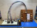
I want to build a marque type chaser but replace what nowadays is usually LEDs with 12v mini E10 incandescent bulbs. The type of chaser that has maybe every 4th bulb on at the same time moving around a square pattern. So probably 16 bulbs in the pattern. Adjustable speed and running at 12vdc. I’ve seen the LED variety but I assume a transistor/mosfet will be needed to handle the switching/load. I’d appreciate a circuit design adapted for this using the common 555/4017 work horses.
 

AnalogKid

Joined Aug 1, 2013
12,045
Every 4th bulb means that the circuit has only 4 outputs no matter now many bulbs in the display. Find the operating current for one bulb, multiply that by the number of bulbs on at one time, and multiply that by at least 5. That is the minimum current rating for the transistors driving the bulbs. You need a 5x margin because incandescent bulbs have a high current surge at turn-on. If the individual bulb current is relatively low, another option is to use driver chips such as the ULN2804. This is an 8-stage driver with built-in transient protection. You need that because a light bulb filament is an inductor that produces a voltage spike when it is turned off. With this part, use one output for each bulb and combine the inputs.

555 > 4017 > 2 x 2804's > bulbs

First pass at a schematic. C2 and C3 are power supply decoupling capacitors for the two IC's. Click on the sch for a larger image.

ak

!!Light-Chaser-2-c.gif
 
Last edited:

Thread Starter

Icanmakeit67

Joined Sep 23, 2018
210
Every 4th bulb means that the circuit has only 4 outputs no matter now many bulbs in the display. Find the operating current for one bulb, multiply that by the number of bulbs on at one time, and multiply that by at least 5. That is the minimum current rating for the transistors driving the bulbs. You need a 5x margin because incandescent bulbs have a high current surge at turn-on. If the individual bulb current is relatively low, another option is to use driver chips such as the ULN2804. This is an 8-stage driver with built-in transient protection. You need that because a light bulb filament is an inductor that produces a voltage spike when it is turned off. With this part, use one output for each bulb and combine the inputs.

555 > 4017 > 2 x 2804's > bulbs

First pass at a schematic. C2 and C3 are power supply decoupling capacitors for the two IC's. Click on the sch for a larger image.

ak

View attachment 332819
That looks doable. I think I have 2804 chips. Thank You so much.
 

AnalogKid

Joined Aug 1, 2013
12,045
2803's also will work. The only difference is that the 2804 has a larger input resistor so it doesn't overload the very low current PMOS IC's of the 1970's. So will 2003's and 2004's, but you will need three of them to cover 16 lamps. Or two 2004's plus two discrete transistors. Lotsa combinations.

GO Buckeyes!

ak
 

Thread Starter

Icanmakeit67

Joined Sep 23, 2018
210
2803's also will work. The only difference is that the 2804 has a larger input resistor so it doesn't overload the very low current PMOS IC's of the 1970's. So will 2003's and 2004's, but you will need three of them to cover 16 lamps. Or two 2004's plus two discrete transistors. Lotsa combinations.

GO Buckeyes!

ak
I have the two 2804s. Discrete resistors? Not sure what you mean. I was going to follow the schematic you put up?
 

AnalogKid

Joined Aug 1, 2013
12,045
Discrete *tran*sistors.

I was saying that you can use the ULN2004 / 2003 in this circuit, but since those parts have only 7 channels per IC you would have to make up the missing channels with discrete transistors.

ak
 

Thread Starter

Icanmakeit67

Joined Sep 23, 2018
210
#1446 12v 2.4 watt E10 base, my bench supply showed .21 amp at 12volts when I tested a few.
Built the lamps on a strip board and breadboarded up the circuit you kindly provided….. works great. Here is a pic. I’d try to put up a link to a short video here in a bit. Again thanks!
 

Attachments

MisterBill2

Joined Jan 23, 2018
27,186
You could just as easily put the four bulbs in series and deal with only a quarter of the current, at 48 volts instead of 12 volts. Then use a CD4017 to drive foul logic-level input mosfets to drive four higher powered mosfets to switch the return to common side of the four series strings.
 

AnalogKid

Joined Aug 1, 2013
12,045
I'm more curious about the eight (foul + four) transistors and the other components.

Also, which topology are you using to create the 48 V supply?

ak
 
Last edited:

MisterBill2

Joined Jan 23, 2018
27,186
The simple way to provide a 48 volt supply for powering a string of 12 volt lights would be a voltage doubler circuit fed from a common 24 volt transformer. Flashing lights do not need a tightly regulated voltage, so the lack of regulation is not a serious problem. OR for AC power, two 24 volt transformer secondaries in series.
That certainly is a good point. In my situation, for development, I would just et the power supply to 48 volts output. But that would not work for an actual project, would it? An alternative would be to switch to six volt bulbs and use just a 24 volt supply. OR two parallel strings of two 12 volt bulbs.
48 volts is common in older telecom systems and so surplus supplies are another option.
 
Top