An LED Chaser based on a 555 and 4017.

Thread Starter

DanielLitwin

Joined Mar 23, 2017
52
https://forum.allaboutcircuits.com/threads/100-led-chaser.81140/
Youcan adjust the couunt to whatever you max 100 count, Something I tried to point ou in my other article is physical layoutof LEDs is arbitrary.

Ahhh this is exactly what I need... is it safe to assume that the LEDs light up in the order that they are labeled? I.e., d1->d2->d3 so on and so forth? I've seen this design on YouTube and the LEDs chased either vertically (in the order that the LEDs are labeled in that schematic) and I've also seen videos where they chase horizontally, but I suppose that could have just been the orientation or placement of LEDs.

-Dan
 

Thread Starter

DanielLitwin

Joined Mar 23, 2017
52
Something like this?

Yes this would work, do you have a schematic for it. Wendy and Bernard have been nice enough to provide schematics but I'm trying to collect as many as possible and assses which ones suit my needs the best. I might even do one initial PCB with multiple chaser schematics split up before I narrow it down to one (our company has a bit of credit with our fab house so cost isn't a concern, especially if I choose a long lead time).
 

dl324

Joined Mar 30, 2015
18,406
Yes this would work, do you have a schematic for it.
What you want would be best implemented with shift registers.

I entered the circuit in a simulator and didn't put much effort in making it neat. If you're really going to consider a moving dot type of display, I'll consider making a cleaner schematic; at least enough so you can get the idea.
 

dl324

Joined Mar 30, 2015
18,406
Yes this would work, do you have a schematic for it.
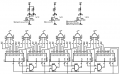
upload_2017-4-10_7-31-58.png
Notes:
  1. Counters drive bar (B) and square wave (S) LEDs.
  2. Other LED drive circuitry could be substituted for 2N7000.
  3. When the counters are reset no LEDs are on. Modify the first counter wiring if you want an LED on at all times, e.g. to keep synchronized with outer ring.
 

Attachments

Thread Starter

DanielLitwin

Joined Mar 23, 2017
52
View attachment 124381
Notes:
  1. Counters drive bar (B) and square wave (S) LEDs.
  2. Other LED drive circuitry could be substituted for 2N7000.
  3. When the counters are reset no LEDs are on. Modify the first counter wiring if you want an LED on at all times, e.g. to keep synchronized with outer ring.
This is exactly what I'm looking for. The .png you uploaded is a little grainy; any way could blow it up in your schematic editor so I can see nets better (the part numbers I can see fine, it's the numerical values that get really fuzzy).

Thanks! :)
 

Thread Starter

DanielLitwin

Joined Mar 23, 2017
52
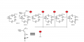
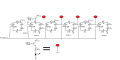
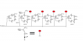
Here's another version that uses shift registers. I used bi-directional to get the effect shown:
I think the OP of post 42 is correct in saying that the vertical LEDs on the square wave should all like up at the same time (that way there's no staggering among the top bar of LEDs); though it would be nice to to use the counters and gates the way you have set up so making a synchronized ring would be easier.
 

dl324

Joined Mar 30, 2015
18,406
I think the OP of post 42 is correct in saying that the vertical LEDs on the square wave should all like up at the same time (that way there's no staggering among the top bar of LEDs); though it would be nice to to use the counters and gates the way you have set up so making a synchronized ring would be easier.
You can sync the ring with whatever number of LEDs you use in the bar/square wave if you make the number in the ring a multiple of the square wave (or bar).

You were pretty clear in your early posts that you wanted the pause in the bar. To remove it, you can drive the LEDs in the square wave edges with the same signal. That will remove circuitry to drive 18 LEDs.

You can save all of us a lot of busy work if you decide what you want before you start designing, or asking others to design, your circuit.
 

Thread Starter

DanielLitwin

Joined Mar 23, 2017
52
Opps I didn't see the schematic; but yes this suits my purposes much better. Also, the OR gates are labelled as FETs (4072N). I'm also assuming that the MOSFETs that are used
You can sync the ring with whatever number of LEDs you use in the bar/square wave if you make the number in the ring a multiple of the square wave (or bar).

You were pretty clear in your early posts that you wanted the pause in the bar. To remove it, you can drive the LEDs in the square wave edges with the same signal. That will remove circuitry to drive 18 LEDs.

You can save all of us a lot of busy work if you decide what you want before you start designing, or asking others to design, your circuit.
Sorry if I gave the impression that I was asking you to do all the work for me; I'm just more familiar with high voltage electronics and I thoughts that's what we did here. It's kind of an evolving design so I can understand why you would think that.

My bad.
 

dl324

Joined Mar 30, 2015
18,406
Also, the OR gates are labelled as FETs (4072N).
The complete part number is CD4072. The N suffix denotes the package type; DIP in this case.

Most people doing circuit design are familiar with 4000 series CMOS. CD4072 is also equivalent to MC14072, HEF4072, ...

The schematic editor I use drops the prefix because it's assumed and avoids cluttering the schematic with information that isn't very useful.

You mentioned using 555 and 4017. The timer prefix is NE, LM, ... The 4017 is in the 4000 series...
 
Last edited:

Thread Starter

DanielLitwin

Joined Mar 23, 2017
52
The complete part number is CD4072. The N suffix denotes the package type; DIP in this case.

Most people doing circuit design are familiar with 4000 series CMOS. CD4072 is also equivalent to MC14072, HEF4072, ...

The schematic editor I use drops the prefix because it's assumed and avoids cluttering the schematic with information that isn't very useful.

You mentioned using 555 and 4017. The timer prefix is NE, LM, ... The 4017 is in the 4000 series...
That makes sense; I'm used to using SMD components so I'm not up on the DIP-lingo, as it were.
 

Bernard

Joined Aug 7, 2008
5,784
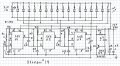
Another outline from 2016, of a marquee display using cascaded 555s with paralleled LEDs. @ 10 mA LED current
Stream # 14 00000.jpg
, should drive 90 LEDs, assuming 4 555s & 4 strings of LEDs. Would operate on lower V like 6 V.

Moderators note: shown image full size.
 
Last edited by a moderator:

dl324

Joined Mar 30, 2015
18,406
I think the OP of post 42 is correct in saying that the vertical LEDs on the square wave should all like up at the same time (that way there's no staggering among the top bar of LEDs)
What frequency were you planning to use? If you look at the first part of my second video (bar display), the pause in the bar wasn't noticeable. I slowed the clock for the latter part so you could discern the behavior at the start and end.
 

Thread Starter

DanielLitwin

Joined Mar 23, 2017
52
The beauty of SMT is that I can swap parts off if I don't like them; or keep it DNP. My last knightrider circuit I put at the top of a design just for fun, I just used a 10uF cap, and two 10ks on the 555 (the one between discharge and threshold was in parallel with a 10k potentiometer). Those are all things I can figure out later but for the most part it won't be lightning fast :)
 
Top