There are NO simple, but accurate, methods for doing what You want.
This is, of course, only my feeble opinion,
and I am definitely NOT qualified to design High-Frequency-Transformers,
I know just enough to be dangerous,
and to know that High-Frequency-Inductors and Transformers are very complex, and fickle to work with.
There are probably people in this Forum who could better answer your question,
but as for whether or not they would be willing to donate the
ridiculous number hours required to teach You all about it, ( in a Forum no less, and for free ),
well, that may be a different story.
There may be commercial-equipment that can provide the answers You are looking for,
.
.
.
There are NO simple, but accurate, methods for doing what You want.
This is, of course, only my feeble opinion,
and I am definitely NOT qualified to design High-Frequency-Transformers,
I know just enough to be dangerous,
and to know that High-Frequency-Inductors and Transformers are very complex, and fickle to work with.
There are probably people in this Forum who could better answer your question,
but as for whether or not they would be willing to donate the
ridiculous number hours required to teach You all about it, ( in a Forum no less, and for free ),
well, that may be a different story.
There may be commercial-equipment that can provide the answers You are looking for,
.
.
.
I have some of these. I know it is too big. I want to show the SSR come in many sizes and work on AC power lines. 50A SSR data sheet Works 47 to 440hz. Input to output isolation 4000 volts.
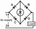
How about a trick I came up with many years ago: Rather than two devices in series, us a silicon diode bridge rectifier and a single control device between the two DC terminals, while the two AC bridge terminals are in series between the AC source and the AC load. Then it can even work with a bipolar transistor, or even a vacuum tube.(I do not recommend that). Only one series device then needs to be controlled. It worked back in 1969 and allowed a single SCR to control both phases of an AC power feed to a transformer.A simple way to regulate a high power DC power supply.
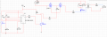
I made some slight modifications: in the RC circuit, the switch has been replaced with an SSR (solid-state relay).
Is there anything else I might need to modify in the RC circuit?
How about a trick I came up with many years ago: Rather than two devices in series, us a silicon diode bridge rectifier and a single control device between the two DC terminals, while the two AC bridge terminals are in series between the AC source and the AC load. Then it can even work with a bipolar transistor, or even a vacuum tube.(I do not recommend that). Only one series device then needs to be controlled. It worked back in 1969 and allowed a single SCR to control both phases of an AC power feed to a transformer.A simple way to regulate a high power DC power supply.
The principle behind my suggestion is that the AC current passing between the two AC terminals of a bridge rectifier circuit is equal to the DC current passing between the + and - terminals. There is a voltage drop, but the current is the same.
How about a trick I came up with many years ago: Rather than two devices in series,
us a silicon diode bridge rectifier and a single control device between the two DC terminals,
while the two AC bridge terminals are in series between the AC source and the AC load.
MOSFETs are turned on/off by the voltage from Gate to Source. They do not care what the voltage is from Gate to Ground!
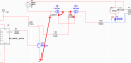
The Gate drive voltage is VCC and GND which is not connected to the MOSFETS. There are two grounds in the page that are not related. If V1 was the power line G! & G3 would likely break. There is an undefined voltage (probably too much) being applied to the Gates.
Why a snubber across T1? I don't see a reason for D1. The snubber will only work for 1/2 the power cycle.
MOSFETs are turned on/off by the voltage from Gate to Source. They do not care what the voltage is from Gate to Ground!
The Gate drive voltage is VCC and GND which is not connected to the MOSFETS. There are two grounds in the page that are not related. If V1 was the power line G! & G3 would likely break. There is an undefined voltage (probably too much) being applied to the Gates.
I can roughly understand what you mean.
Although this switch will be replaced by an SSR, I’ve considered this issue: can the ground for the driver be shared with the ground of the AC circuit?
I placed this snubber because I saw some examples and content in certain information and articles.
Here’s my thought (though I’m not sure if it’s correct):
When I switch the circuit, the transformer generates a back electromotive force (EMF) that could affect my other components.
Initially, I only connected a diode.

 Facebook
 Google
 GitHub
 Linkedin