SPST Switch + Mosfet to control H Bridge?

Thread Starter

cpyne

Joined Apr 21, 2023
10
Hi All,

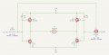
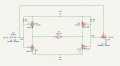
I am trying to build a circuit to control a open/close of a linear actuator via an h-bridge on a timer. The timer I'm using only has a SPST open/close switch which I want to have open the linear actuator when in the On position and close the linear actuator when on the Off position. I tried to do this using a VP3203N mosfet to act as the second switch leg, but this doesn't seem to be working. Everything works fine if remove the VP3203N and jumper the power mosfets to the correct on/off position, but I can't seem to get the VP3203N to handle this

Can anyone look at my diagram and let me know if I've got a flaw in my design here? Thanks!
 

Attachments

crutschow

Joined Mar 14, 2008
38,316
look at my diagram and let me know if I've got a flaw in my design here?
Two, actually:

The gate-source resistors on the N-MOSFETs means the gate voltage goes to 6V, not 12V when the switch is open, thus both the N and P MOSFETs are likely conducting.
Remove the bottom N-MOSFET gate resistors.

Q4 needs to be configured as an inverter with the source to ground, the gate to the switch output, and the drain to the Q6 and Q10 gates (with one resistor to +12V).
Remove R13 and R15.
 

Thread Starter

cpyne

Joined Apr 21, 2023
10
Thanks @crutschow . I'm still having some problems with this. I've updated the diagram to make sure I follow what you're saying. Does this look like what you're thinking?
 

Attachments

crutschow

Joined Mar 14, 2008
38,316
Does this look like what you're thinking?
Yes, but there's a small error that's my mistake. :oops:
The circuit will work, if the switch goes to ground, not 12V.

If you want the switch to stay connected to 12V, then move R9 (but not R14) from +12V to ground.
 

Thread Starter

cpyne

Joined Apr 21, 2023
10
Thanks. I'm close, but still have an issue somewhere. With the switch open, I see Q11 and Q6 turn on and a test LED I have in the middle in place of the motor turns on. With the switch closed, Q10 and Q7 don't seem to want to turn on and another test LED in the other direction never comes on. If I pull out Q4 and jumper GND right over to where its drain was connected, then LED #2 comes on fine. Maybe I damaged Q4 somehow?? I'll have to play around with it some more tomorrow, but thank you for the tips here
 

Thread Starter

cpyne

Joined Apr 21, 2023
10
@crutschow After much trial and error, here is what I ended up with. I could not seem to get the VP3203N to work, so I'm thinking I either damaged it somehow or maybe P-channel wasn't the right component to use here? I had an extra IRLZ44N which I put in as my #2 switch and it seems to work great. Thanks for your help pointing me in the right direction here. If you've got any other thoughts on this design, please let me know.
 

Attachments

MisterBill2

Joined Jan 23, 2018
27,164
This can easily be done with a CMOS hex inverter IC, but doing it with a single mosfet is not nearly as easy. That scheme will also need a single resistor to pull the switch output to the opposite of where it pulls when it is closed.
If the one IC plus one resistor scheme is OK I wil describe the circuit.
 
Top