It's right-ish, but you can make it better.
Move R23 to between Q8 and R17. Put D7 across R17. Then put 10Ω where R23 used to be.
That way you have a solid drive to the MOSFET from the complementary emitter follower, and the gate voltage limiting is done on the input to the emitter follower rather than the output.
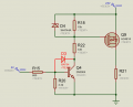
In my schematic:
By using a D1 Baker Clamp it’s allowed to use a Ib:Ic ratio of Q3 about 1:1 (even harder) since the Q3 doesn’t reach the saturation then.
I want to emphasise that component creating a huge delay is a Q3 since it is connected in e̶m̶i̶t̶t̶e̶r̶ ̶f̶o̶l̶l̶o̶w̶e̶r̶ common emitter configuration.
See results at 50kHz switching frequency:
(Blue is V2 input signal, green is R4 load current)
Without Baker Clamp with Q3 Ib:Ic ratio 1:6:
With Baker Clamp involved and Q3 Ib:Ic ratio 1:1:
Edit: I forgot to place a 47k between Gate and Source of P-mos.
In my schematic:
By using a D1 Baker Clamp it’s allowed to use a Ib:Ic ratio of Q3 about 1:1 (even harder) since the Q3 doesn’t reach the saturation then.
I want to emphasise that component that creates a huge delay is a Q3 since it is connected in emitter follower configuration.
See results at 50kHz switching frequency:
(Blue is V2 input signal, green is R4 load current)
Apologies for being pedantic but it's not an emitter follower, it's a common emitter circuit.
(And the Baker clamp is an excellent idea) A small MOSFET (2N7000) might also work well. @sghioto the TS might need complementary drive and he might not. He hasn't said what frequency it is switching at!
Apologies for being pedantic but it's not an emitter follower, it's a common emitter circuit.
(And the Baker clamp is an excellent idea) A small MOSFET (2N7000) might also work well. @sghioto the TS might need complementary drive and he might not. He hasn't said what frequency it is switching at!
It's right-ish, but you can make it better.
Move R23 to between Q8 and R17. Put D7 across R17. Then put 10Ω where R23 used to be.
That way you have a solid drive to the MOSFET from the complementary emitter follower, and the gate voltage limiting is done on the input to the emitter follower rather than the output.
The most of (turn off) delay now causes the Gate charging, so changing the gate resistor from 22ohm to 10ohm should improve that. But for 1Mhz, no way.
Btw, i would use a 15V zener so it doesn’t conduct during normal operation, during overvoltage only (>30V Vcc).
Something I have done many times in production.
A1=standard Gate Driver IC.
M1=PMOSFET.
C3 ac couples the signal to the Gate.
I set the RC time constant to 10x the switching frequency.
R4 turns off the MOSFET when there is no signal.
Gate voltage: off= 0.7V above the Source voltage. On= Source voltage - IC supply voltage - 1V.
Will not work at 100% on time. Will work from 0% on to 90% on time.
switch(Scanled)
{
case 0: Select_7SEG4_B(1,0,0,0,0,0,0); break;
case 1: Select_7SEG4_B(0,1,0,0,0,0,0); break;
case 2: Select_7SEG4_B(0,0,1,0,0,0,0); break;
case 3: Select_7SEG4_B(0,0,0,1,0,0,0); break;
case 4: Select_7SEG4_B(0,0,0,0,1,0,0); break;
case 5: Select_7SEG4_B(0,0,0,0,0,1,0); break;
case 6: Select_7SEG4_B(0,0,0,0,0,0,1); break;
}
 Facebook
 Google
 GitHub
 Linkedin