Yes, I understood that. I just wanted to make sure I understand how to do the test. I told you I’m an amateur, haha. My question is, do I put the red wire in contact with the electrical foot contact on the bulb and the white wire on the screw contact, then turn the armature to get the bulb to light?
Yes, it is easier if you have a ES lamp holder to screw the bulb into, but just place the lamp contacts each one to R & W and then B & W board terminals and power on and turn the speed control pot to see any results for each.
Max.
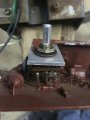
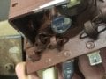
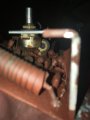
Well, got all the wiring replaced, put the motor back together, and same results. Tried the light bulb test, couldn’t get it to light, probably because I couldn’t turn it fast enough. But I did measure voltage and current with the multimeter, so it’s definitely producing. It must be a problem within the circuit board. I’m posting a picture of the speed switch (not sure if that’s what it called, has 3 prongs running into the circuit board). I’m also posting 2 additional pics of the what I think is a resister that’s heating up and the blueish capacitor I think? The blueish item seems to be damaged, but no sure if that would affect anything. Any other ideas?
The "bluish thing" is a three terminal variable resistor, and if it is damaged that might be the source of the problem, or not. But since the motor seems to be in OK condition it may make more sense to buy a new speed controller made for universal motors such as this. Open loop speed control can produce acceptable results on a lathe, since the basic control requirement is ueually either "Fast" or "Slow", although some talk about specific surface speeds for specific cutter. And you might find it satisfactory to simply use a variable voltage DC supply to drive the motor.
The "bluish thing" is a three terminal variable resistor, and if it is damaged that might be the source of the problem, or not. But since the motor seems to be in OK condition it may make more sense to buy a new speed controller made for universal motors such as this.
It appears to be a MOV metal oxide varistor otherwise known as a VDR voltage dependant resistor.
IMO the jury is still out on the motor technology, shunt or series field, IF a Universal motor a AC Triac controller would run it.
Max.
If that "bluish thing" is indeed a MOV used for circuit protection it may have done it's protection service and become permanently short circuited. I have experienced that in several instances. It would certainly explain the overheating series resistor as well. So checking that device to see if it has gone to a permanently low resistance will let you know. But it also looks like a variable resistor that has been glued into a fixed position.
If it has wire leads then it is probably the varistor as Max suggested, while if the back side looks like metal, and the leads soldered into the board are flat , then it is more likely the variable resistor.
If you can take another picture that shows the whole thing, including the leads,the answer will be more certain.
Jdi2010,
Reading your post #64 you seem to have misunderstood the test with the lamp. You seem to have connected the lamp to the motor. It should have been connected to the wires FROM the control board that would normally be connected to the motor.
The "bluish thing" is a three terminal variable resistor, and if it is damaged that might be the source of the problem, or not. But since the motor seems to be in OK condition it may make more sense to buy a new speed controller made for universal motors such as this. Open loop speed control can produce acceptable results on a lathe, since the basic control requirement is ueually either "Fast" or "Slow", although some talk about specific surface speeds for specific cutter. And you might find it satisfactory to simply use a variable voltage DC supply to drive the motor.
Where could I find a speed controller and how would I know it’s a suitable this motor? Second, would I just simply remove the speed controller from the circuit board and attempt to solder the new one on? Maybe it would make more sense just to get the variable DC voltage supply drive for the motor. (I assume the variable voltage will control the speed?). And again, where would I find that and make sure it’s the right specs for my motor? Thanks.
It appears to be a MOV metal oxide varistor otherwise known as a VDR voltage dependant resistor.
IMO the jury is still out on the motor technology, shunt or series field, IF a Universal motor a AC Triac controller would run it.
Max.
Jdi2010,
Reading your post #64 you seem to have misunderstood the test with the lamp. You seem to have connected the lamp to the motor. It should have been connected to the wires FROM the control board that would normally be connected to the motor.
Ah thanks, that is what I was doing. I don’t understand why that doesn’t work though. Isn’t it current and amperage coming directly off the motor, and why won’t that provide what’s needed to light the bulb?
A series wound motor will not work as a generator. A shunt wound one MAY work as a generator if there is enough residual magnetism in the metal of the field winding. A permanent magnet motor would work as a generator but even if you had one it would need to be rotated close to its rated speed when running as a motor. (For example drive it with an electric drill.) The reason for connecting the lamp to the output of the controller to see if it is giving any output without overheating. The suggested lamps would require less power than the motor.
Where could I find a speed controller and how would I know it’s a suitable this motor? Second, would I just simply remove the speed controller from the circuit board and attempt to solder the new one on? Maybe it would make more sense just to get the variable DC voltage supply drive for the motor. (I assume the variable voltage will control the speed?). And again, where would I find that and make sure it’s the right specs for my motor? Thanks.
The exact model is either a KBIC-125 or KBIC-120 (too long ago to remember which). Max current is set by a high-wattage resistor (probably same function as the wire wound resistor in your device that gets hot). I got mine new off ebay for about $90 circa 2003. Used units are available at about half that today. Be careful with a used controller. I got one once that was "removed from a working environment." Yes, it was a working environment, but the controller was removed because it had burned up an SCR and PCB track (both repairable).
There are so many unanswered questions about your problem that it seems premature to start buying stuff. Your controller may be easily fixed if it is just the MOV. Your motor may be bad. While a DC power supply might work for testing, my feeling is that would be a bulky, expensive, and second rate way to control that lathe's motor.
BTW, the above lathe is a metal working lathe. For woodworking, I don't believe you will really need the continuously variable speed. A couple of stepped pulleys may work just fine with an inexpensive AC induction motor.
If that "bluish thing" is indeed a MOV used for circuit protection it may have done it's protection service and become permanently short circuited. I have experienced that in several instances. It would certainly explain the overheating series resistor as well. So checking that device to see if it has gone to a permanently low resistance will let you know. But it also looks like a variable resistor that has been glued into a fixed position.
If it has wire leads then it is probably the varistor as Max suggested, while if the back side looks like metal, and the leads soldered into the board are flat , then it is more likely the variable resistor.
If you can take another picture that shows the whole thing, including the leads,the answer will be more certain.
The Triac 'Dimmer' style controllers are relatively cheap, but you would need to ensure the motor is a Universal version first, these have the power connected across the series field and armature.
No third wire, white, in your case.
The KB and treadmill style controllers will not run a series (Universal) motor.
Max.
Ah thanks, that is what I was doing. I don’t understand why that doesn’t work though. Isn’t it current and amperage coming directly off the motor, and why won’t that provide what’s needed to light the bulb?
Yes, make sure you use the lamp across the board outputs as already indicated, the motor is not connected at all.
If the board is OK, it should indicate the nature of the motor.
Max.
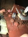
Here’s some more pictures of the suspect varistor. It the first photo you can see there’s some writing on the back of the brass plate. Unfortunately the speed controller is in the way and I can’t see what the numbers say.
The Triac 'Dimmer' style controllers are relatively cheap, but you would need to ensure the motor is a Universal version first, these have the power connected across the series field and armature.
No third wire, white, in your case.
The KB and treadmill style controllers will not run a series (Universal) motor.
Max.
We have seen the pictures of the brushes and thus most of us have concluded that it is indeed a universal motor. In addition, looking at the windings in the photo, which are not that many turns of fairly heavy wire, another conclusion is that it is most probably a universal series type motor, with a connection for monitoring the armature voltage.
Who is Most of us?
There is an equally convincing case that the white is a common as the other two register +ve with respect to it evidently.
As to the resistance of the windings, they constitute around the equal resistance for one as do each in series.
A Universal motor on DC has a higher RPM than on the same AC because it does not posses the inductive reactance that it has with AC. So the low resistance is still presented.
It may well be that it is in fact a Universal motor. But the evidence is by no means conclusive.
Max.
 Facebook
 Google
 GitHub
 Linkedin