
 Facebook
 Google
 GitHub
 Linkedin
Good Day all,
I have two motor controllers, one from a pottery wheel and one from a semi-industrial sewing machine. Both are still commercially available so it's not an emergency to repair these but I am interested in learning more about them and how they have failed but only have basic electrical training from technical school.
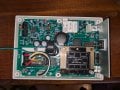
The first board, from a pottery wheel, I can troubleshoot it just past the supply components. The 110V comes into the circuit on the lower left corner of the board through a three pin connector. There is a 10A fuse immediately after, followed by a 0.1 microfarad "suppression" capacitor (not sure if suppression is correct or not but I read it while looking online), then more capacitors I cannot identify, a transformer, resistor, and the power then goes out to the board components. There are two larges caps and a few smaller ones and none of them appear to have leaked out or popped. They tested correctly on my fluke, but that was testing while on the board, do I need to remove them for correct testing? On the right side there are a number of IGBTs which I assume are for the motor outputs but I don't know.
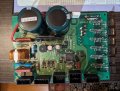
The second board from the sewing machine, seems more simple and I already got a bit of help on it. When i bought the machine it blew fuses immediately. Speaking with a distributor they had me check the rectifier and FET which were both bad. I replaced them and got the board to start powering on without popping the fuse but it doesn't provide the proper output so they have simply told me to "replace the board or upgrade the system". Again I can identify the majority of the basic components but not much past that.
Is there any sort of flow chart/cheat sheet for the order of operations for checking through a board to verify components? Are there components which have to be desoldered from the board to be correctly checked? Any advice would be appreciated.
I have two motor controllers, one from a pottery wheel and one from a semi-industrial sewing machine. Both are still commercially available so it's not an emergency to repair these but I am interested in learning more about them and how they have failed but only have basic electrical training from technical school.
The first board, from a pottery wheel, I can troubleshoot it just past the supply components. The 110V comes into the circuit on the lower left corner of the board through a three pin connector. There is a 10A fuse immediately after, followed by a 0.1 microfarad "suppression" capacitor (not sure if suppression is correct or not but I read it while looking online), then more capacitors I cannot identify, a transformer, resistor, and the power then goes out to the board components. There are two larges caps and a few smaller ones and none of them appear to have leaked out or popped. They tested correctly on my fluke, but that was testing while on the board, do I need to remove them for correct testing? On the right side there are a number of IGBTs which I assume are for the motor outputs but I don't know.
The second board from the sewing machine, seems more simple and I already got a bit of help on it. When i bought the machine it blew fuses immediately. Speaking with a distributor they had me check the rectifier and FET which were both bad. I replaced them and got the board to start powering on without popping the fuse but it doesn't provide the proper output so they have simply told me to "replace the board or upgrade the system". Again I can identify the majority of the basic components but not much past that.
Is there any sort of flow chart/cheat sheet for the order of operations for checking through a board to verify components? Are there components which have to be desoldered from the board to be correctly checked? Any advice would be appreciated.
Attachments
-
 313.7 KB Views: 8
 -
 192.6 KB Views: 8





