Troubleshooting lathe motor

Thread Starter

Jdj2010

Joined Oct 21, 2018
37
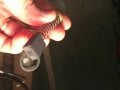
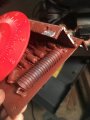
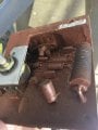
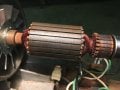
Problem I’m having with an old lathe that I believe is electrical in nature. It turns on, spins for a second, then stops or hesitates. A large resistor on the circuit board heats up fast and smokes. I checked all moving parts and no binding. I replaced all wiring, didn’t solve the issue. Could this be caused by bad brushes? They do look worn. Any other ideas as to a possible culprit? Thanks.
 

jpanhalt

Joined Jan 18, 2008
11,087
What lathe do you have? Have you considered switching to a DC motor and an appropriate control? That is what the Monarch 10EE uses, which is the Cadillac of manual lathes.
 

MaxHeadRoom

Joined Jul 18, 2013
28,696
The com on the motor does not look that bad, I would run a check the motor on a DC supply for a period of time, off say a automotive battery.
The resistor is most likely to detect the current limit, there are ex- Treadmill controllers that would run that motor, or those made by KB electronics.
Max.
 

Thread Starter

Jdj2010

Joined Oct 21, 2018
37
The com on the motor does not look that bad, I would run a check the motor on a DC supply for a period of time, off say a automotive battery.
The resistor is most likely to detect the current limit, there are ex- Treadmill controllers that would run that motor, or those made by KB electronics.
Max.
Thank
 

Thread Starter

Jdj2010

Joined Oct 21, 2018
37
Thanks Max. I’m very much beginner level here. Can you go into detail (maybe step by step) what I would need to do based off your description?
 

MaxHeadRoom

Joined Jul 18, 2013
28,696
First, is it a wound field motor or does it have perm. magnets?
If the motor leads are shorted, you would see a braking effect when trying to spin the shaft if P.M.
If P.M. connect the two leads to an automotive battery and see if it appears to run OK in both directions.
Can you post a picture of the whole control board?
Max..
 

jpanhalt

Joined Jan 18, 2008
11,087
Do you have any way to measure the actual current draw? I doubt it is the resistor. More likely, something is trying to draw too much current. Shorts in the armature? If it is an integral problem in the motor, it is probably cost prohibitive to fix.

I did a little research on that wood lathe and saw some images of designs where people used a belt drive from a typical motor.
 

MaxHeadRoom

Joined Jul 18, 2013
28,696
I would do the 12vdc test on the motor, feed the field and the armature from the same 12v.
If the motor is OK, one of the KB drives would probably fit the bill.
It may be worth looking at a ex treadmill motor and drive.
Some of those field winding's look a little black, hard to see if this is a overheating result.
What is the voltage supply for the drive?
Max.
 

MisterBill2

Joined Jan 23, 2018
18,566
My suggestion is that before anything else, with power disconnected, check for short circuits to the frame on both the stator (field) and on the armature. Next, verify continuity of the field winding, and then, with the armature installed and the brushes in place, check for no large changes in the resistance as the armature is slowly rotated. If the motor nameplate gives a field voltage or current that information would hel evaluate the situation. If the field is not right then it will not run very well at all.And if the field is wound for series and connected as a shunt, that would be a big problem.
Did this lathe ever run correctly for you?? If not, then it may not be wired right, Wiring errors can make searching for the problem a muc more interesting experience.
 

MaxHeadRoom

Joined Jul 18, 2013
28,696
I would doubt very much that would be a wound a series field, they are very hard to control RPM without permanent load or feedback of some kind.
Early DC motors for this function were typically shunt field.
Max.
 

Thread Starter

Jdj2010

Joined Oct 21, 2018
37
Tested the continuity on all wires into the motor and showed 0 resistance. Checked the circuit board and showing 5-7 ohms. I don’t have the equipment to check current draw for the motor unfortunately.
 

MaxHeadRoom

Joined Jul 18, 2013
28,696
Did you you do the 12vdc test with a automotive battery?
To test the winding leakage to frame, use the ohm meter.
I would have expected a few ohms on the field at least instead of 0Ω?
By zero you mean 'shorted' right?
Max.
 

Thread Starter

Jdj2010

Joined Oct 21, 2018
37
Did you you do the 12vdc test with a automotive battery?
To test the winding leakage to frame, use the ohm meter.
I would have expected a few ohms on the field at least instead of 0Ω?
By zero you mean 'shorted' right?
Max.
That’s correct, 0 resistance. There are 3 wires that go from circuit board to motor. The wiring diagram doesn’t specify what goes to what. I assume black and red are stator/rotor (not sure which is which), and white is common. I connected the first lead on the ohm meter to the black wire, and then the white wire, and measured 0 ohms. Same with the red wire. I assume that means there’s no problems with the wiring in the coils? Unfortunately I don’t have a 12V battery to use unless I pull one off my car. I’ll check with my neighbor tomorrow and see if he has one I can borrow.
 
Top