Maybe I just need to cut the wire open at the motor and follow the paths of each wire into the motor since I don’t seem to be getting anywhere with diagnosing the problem. At least then we’ll figure out the reason for the 3 wires.
My guess is that one wire, probably the white one, is used to monitor the armature voltage as part of a feedback scheme. Thus, if nothing has fried, you should clean the comutator so that the feedback voltage would be correct. Simple to do and a reasonable idea. But now a question: Why did you need to replace a wire? or wires? And what is the chance that the connection is now not quite right? That would explain incoreect operation without there being anything wrong with the motor or the control circuit board.
My guess is that one wire, probably the white one, is used to monitor the armature voltage as part of a feedback scheme. Thus, if nothing has fried, you should clean the comutator so that the feedback voltage would be correct. Simple to do and a reasonable idea. But now a question: Why did you need to replace a wire? or wires? And what is the chance that the connection is now not quite right? That would explain incoreect operation without there being anything wrong with the motor or the control circuit board.
Do you recommend sanding the commutator with 2000 grit sand paper or will that destroy it?
In reference to the wire, when I opened the unit the insulation on the wires was brittle and severely cracked, with exposed wire. Basically a short waiting to happen. The wire that was still in the original conduit was ok, so I cut the cunduit back a little ways and soldered in the replacement wire. So I can still see the original wire colors to make sure to wire correctly. Not to mention, the motor is doing the same exact thing it was doing before I replaced the wire. So pretty sure all is in order there.
If the cleaning of the commutator doesn’t solve anything, I’m going to cut the conduit down to the motor and physical follow the wires in to determine what goes to what.
2000 grit is finer than you need, but if that is what you have, use it, but gently. And avoid touching the portion of the commutator bars that connect to the windings because that part is subject to damage. And only sand enough to expose the copper. It looked like the brushes were long enough so that they still had adequate force against the commutator, which should be possible to verify wen you assemble it.
Maybe I just need to cut the wire open at the motor and follow the paths of each wire into the motor since I don’t seem to be getting anywhere with diagnosing the problem. At least then we’ll figure out the reason for the 3 wires.
That might settle some theories as to what type of motor, I doubt the 3rd wire is for some kind of feed back, it certainly would not make any sense for a series motor, also I don't see that age of drive being that sophisticated, it seems fairly old technology.
Max.
Do you recommend sanding the commutator with 2000 grit sand paper or will that destroy it?
If the cleaning of the commutator doesn’t solve anything, I’m going to cut the conduit down to the motor and physical follow the wires in to determine what goes to what.
I would be careful on using emery on a com, IF you do, clean it off, slots included, with contact cleaner using an old toothbrush, then wipe it clean, this removes any carbon or emery dust from the slots.
There are specialized products for polishing a com, often done when the motor is running or rotated in situ !
Max.
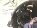
So I took apart the stator to see where all the wires go. I kind of wish I hadn't because now I can see what a mess the wires are. The insulation is cracked to oblivion and the metal from each are definitely in contact with each other coming into the case. I'll input the photos in the next post. But here's a description of what I can see:
Out of the conduit:
1) Black wire goes directly to brush 1.
2) Red wire goes into coil 1.
3) White wire goes across (between) stators and into coil 2.
Other observations:
1) There's a black wire that joins the 2 sides of the coils (has electrical tape in the center?)
2) There's a black wire that goes across and connects to the other brush.
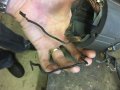
Maybe I should cut and solder the wires and apply shrink wrap and see how it runs. Maybe there was a short. I'm a little suspicious since the black wire joining the 2 coils is taped in the center (was there a self repair job at some point?). I'm going to remove the tape and investigate if it looks like a amateur solder joint, which could indicate tampering with original design. Other than that, I'm not sure what else to do. The wiring coming in is a disaster. It's just old and cracked up.
I apologize in advance due to my limited knowledge of how to draw electrical diagrams, so this crude drawing is the best I can do to illustrate where the wires are going.
See photo attached:
-The red wire goes into the field coil. I followed where the wire comes out of the field coil, and jumps across to the other coil. From there the white wire comes out and returns into the conduit.
-One brush connects directly into the coil with an internal wire. It appears that it just joins into the field coil circuit and continues the same route over to the other field coil and out the white wire.
-The other brush is wired directly from the black wire coming out of the conduit.
What I can’t understand is why the red wire feeds into the field coils, while the brush wire also feeds into the same field coils. Without a diagram of the circuit board, I’m not sure how to figure this out unless you have a theory as to why it was designed this way.
First, the diagram is totally adequate and easy to follow, so thanks for such a good effort. It also conveys the information required very well. Next, the circuit is exactly what I guessed it would be. Connections to both sides of the armature for feedback purposes, at least I think that is the reason. So it would be possible to run the motor without feedback for speed control if you chose to do that.
Probably the connection between windings is OK, since it would not run very well without a field current, I don't think.
Finding a complete circuit diagram will certainly make solving the problem a lot easier, if it can be done.
What I see is possibly a shunt motor where both armature and field have a common and each are fed from a separate supply.
Probably the field is a constant and the armature voltage varied.
Too bad about the extensive Glyptal conformal coating otherwise it would be relatively easy to reverse-engineer the board.
Max.
Thanks all. All I can do at this point is finish replacing the wire and see if it works. If there is something wrong with the coils or circuit board, then there’s probably nothing I can do anyway.
In post #13, I mentioned some pictures on the Internet of that lathe fitted with a belt drive motor. Of course, not all labels are accurate. If the current motor is scrap, I would certainly look into fitting the lathe with a new motor with or without a belt drive. Most of the comments considered that to be a pretty good lathe for the home shop.
@Jdj2010 it would be interesting to see what occurs when connecting a 60w or 100w filament bulb across either white (common) to red or white to blk and rotate the pot, if the board is OK, it may give an idea how it is being controlled.
Max.
@Jdj2010 it would be interesting to see what occurs when connecting a 60w or 100w filament bulb across either white (common) to red and white to blk and rotate the pot, if the board is OK, it may give an idea how it is being controlled.
Max.
I actually tried that, but I can’t remember was combination of wires I used. The bulb didn’t light up. So do I simply place, for example, the red wire on the bottom of the bulb, and the white wire on the bottom of the bulb, and rotate the armature? I should see some lighting of the bulb?
 Facebook
 Google
 GitHub
 Linkedin