My suggestion is that before anything else, with power disconnected, check for short circuits to the frame on both the stator (field) and on the armature. Next, verify continuity of the field winding, and then, with the armature installed and the brushes in place, check for no large changes in the resistance as the armature is slowly rotated. If the motor nameplate gives a field voltage or current that information would hel evaluate the situation. If the field is not right then it will not run very well at all.And if the field is wound for series and connected as a shunt, that would be a big problem.
Did this lathe ever run correctly for you?? If not, then it may not be wired right, Wiring errors can make searching for the problem a muc more interesting experience.
My neighbor gave it to me and said it ran fine in the past but he hasn’t used it in years. He said it probably needs new brushes. I’m trying to locate the size brushes I need online to see if that solves the issue. That test you were talking about with rotating the armature, I assume you’re saying to connect one lead to the armature wire and one to the common, and check the ohm reading? And what specifically would I be looking for?
You should be able to trace which conductor feeds the armature and which the field?
Just for the heck of it, connect the armature conductor to the field conductor , I assume the third is common to each?
Spin the shaft as fast as possible and see if it self generates. i.e. DC voltage on the output.
Max.
First, power must be disconnected from the motor so that there is no chance of shock or damaging the meter.
To check for short circuits to the frame one lead from the ohm meter is connected to the frame and the other lead is connected to each motor wire, one at a time. Also, check the brush connections for continuity to the frame of the motor.
I am wondering about the zero resistance reading. Is that between the different wires? or from one end of the wire to the other, And an important question here is the ohm meter resistance range used. If you are using an analog meter with a pointer, the range should have no more than 50 ohms at the half scale point. The resistance reading that I would expect would be between 5 ohms and 20 ohms, so with a meter with 2000 ohms at mid scale the resistance would look like zero. A digital meter should be used on it's low resistance range if it does not automaticaly change ranges. When checking for short circuits use a higher resistance range.
The commutator does need to be cleaned up, use very fine sandpaper to remove the black, while being very careful to not damage any of the wires connected to it. And the brush looked like it was not worn much at all. What I think I saw was just two wires from the motor, one red and one black. In that case, assemble the motor, after cleaning up the commutator, make sure that it turns freely, and then try running it on the 12 volts from a car battery.It may not run very fast, but that will tell you that the motor is in running condition.
I would doubt very much that would be a wound a series field, they are very hard to control RPM without permanent load or feedback of some kind.
Early DC motors for this function were typically shunt field.
Max.
You should be able to trace which conductor feeds the armature and which the field?
Just for the heck of it, connect the armature conductor to the field conductor , I assume the third is common to each?
Spin the shaft as fast as possible and see if it self generates. i.e. DC voltage on the output.
Max.
First, power must be disconnected from the motor so that there is no chance of shock or damaging the meter.
To check for short circuits to the frame one lead from the ohm meter is connected to the frame and the other lead is connected to each motor wire, one at a time. Also, check the brush connections for continuity to the frame of the motor.
I am wondering about the zero resistance reading. Is that between the different wires? or from one end of the wire to the other, And an important question here is the ohm meter resistance range used. If you are using an analog meter with a pointer, the range should have no more than 50 ohms at the half scale point. The resistance reading that I would expect would be between 5 ohms and 20 ohms, so with a meter with 2000 ohms at mid scale the resistance would look like zero. A digital meter should be used on it's low resistance range if it does not automaticaly change ranges. When checking for short circuits use a higher resistance range.
Ok. I checked for shorts and no movement on the meter. I am using an old vintage analog ohm meter that my dad gave me years ago. Honestly, it 0’s out at 5 ohms, so I was having to use that as my zero point. (Yes, I tried to use the adjustment knob with no success). So maybe my meter is no good. I’ll try to borrow one from my neighbor today and see what readings I get.
Ok. I checked for shorts and no movement on the meter. I am using an old vintage analog ohm meter that my dad gave me years ago. Honestly, it 0’s out at 5 ohms, so I was having to use that as my zero point. (Yes, I tried to use the adjustment knob with no success). So maybe my meter is no good. I’ll try to borrow one from my neighbor today and see what readings I get.
On all of my analog meters, when the low ohms will not zero at "zero " the battery needs to be replaced. On one of them it also meant that the range switch needed a bit of contact cleaner applied to the contacts. Replacing the battery is also a good idea since often weak batterys will start leaking.
You have had the motor apart it should not be hard to trace the few conductors involved to make a sketch of the motor connections, I see the two exiting the stator for the field windings, where do they go to and how are the brush conductors connected, also how many go back to the circuit board?
Max.
Ok, maybe I don’t understand exactly how a DC motor works. Is there a power and return on the stator and just power going to the armature? That would explain 3 total wires going to the motor.
With a DC motor with a wound field there are two methods series field or shunt (parallel) field.
In the first case there is two conductors and the field and the armature are in series with each other, and the way to obtain reversal is to reverse either field or armature conductors, this motor has very poor RPM control as it tend to operate in a uncontrolled or runaway condition when unloaded it does have very high torque however.
The parallel connected is just that, the field is connected parallel to the armature, and reverses by the same method.
In each case there is just two conductors required to feed it, but if reversal is required, then all four conductors are required in order to switch direction.
In some case, the shunt motor has a completely separate supply for the field winding.
Max.
Looking at the photos of the motor back in post #12, the field winding looks like not that many turns of fairly heavy wire, for a motor this size. So I am thinking that it is probably a series wound motor, with the red and black at ends of the split field windings, half on each side, and the two brush holders connected to the opposite ends of the field. That is the arrangement that I have seen in the majority of electrical tool motors.. The presence of a third wire does make it interesting, please le us know what you find.
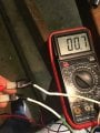
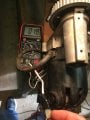
I found out some interesting things today conducting some tests. First, it must be a series motor if I’m thinking correctly. Attached photo, shows when checking continuity between each of the 3 wires to each other, it’s registering about .9 to 1.5 ohms. Also, checking each wire to the commutator, also showing similar ohm readings. This tells me all are connected in series, correct?
2nd test I conducted was removing each of the 3 wires individually and turning on the motor to see what happened. Here’s the results:
1) Black wire disconnected: does not run. (Indicates is the main power source)
2) White wire disconnected: motor runs smoothly at first but then speeds up uncontrollably, to the point I didn’t feel comfortable letting it go any longer. (Indicates possibly the speed control source?). With this reattached the operation was again jerky and sporadic.
3) Green wire disconnected (this was the red wire I had to replace and is green now): motor immediately over speeds (I cut it off immediately because it was so aggressive). (I’m not sure what this would indicate that this wire does??)
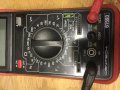
Voltage measured through black wire to motor is 107V. I’m still working on how to measure current. I put a picture of the multi meter I borrowed and I’m not sure which setting to use. I put it on 20A, put it in series with the circuit on the black with power on, but no reading? And the motor didn’t turn on. Maybe current was a lot to pass through multimeter?
Possibly, but not necessarily, say it is a shunt motor and when you removed the field it ran away, this would be normal if removing the field on a shunt connected motor.
I would like to see a sketch of the three conductors and exactly where each end up or are connected in the motor.
Is it possible to come up with a diagram of the conductors and where they are connected in the motor?
I find it still odd that three connections go back to the drive, unless the field has a separate supply, and one conductor is common to both.
Max.
 Facebook
 Google
 GitHub
 Linkedin