Tachometer suddenly died, wondering if the chip is likely still operational.

Thread Starter

Stuntman225

Joined Apr 28, 2026
76
Mmm, I thought you were building it on a PCB. I’m not keen on using that type of prototype system at the best of times, but especially when there are high frequency spikes flying around. I urge you to do a careful compact layout on strip board with the processor in a turned pin socket so you can take it out for uploading code.
A PCB will come eventually, but i wanted to get the whole project working first before I purchased one. I'll try and get some strip board to do prototyping with.
 
Further thoughts. Instead of 2 x 33K resistors for the coil input try 3 x 10K 1/2 watt resistors in series, soldered in the line away from the electronics. For safety, cover with insulation, maybe ptfe or heatshrink - okay to test bare if you are careful. They should not get hot, the 1/2W metal oxide resistors are necessary to withstand the voltage. I don't think the opto is seeing enough current. Try without the processor. 33K pullup resistor instead of 4K7 which you may be able to leave out eventually by using input_pullup in the code. Check this first before inserting the ATtiny. And the 5nF capacitor may be too large - possibly not necessary at all if you are using my spike filtering code. 1nF may be a compromise but try without it first. Seeing the ignition pull down the opto collector to near ground for about 1ms is the target
 
I'm wondering how it's going? I don't have a suitable car so I'm thinking of building a tester using an old coil, replacing the points with a 600V MOSFET (protected by a TVS) as I'd really like to understand why it isn't working.
 

Thread Starter

Stuntman225

Joined Apr 28, 2026
76
I'm wondering how it's going? I don't have a suitable car so I'm thinking of building a tester using an old coil, replacing the points with a 600V MOSFET (protected by a TVS) as I'd really like to understand why it isn't working.
I took a break this weekend on the project, and i'm waiting on a few parts to arrive tonight. I hope to have a fairly large update tomorrow.
If you had any small engines you could build a circuit to test with one of them.
 

Thread Starter

Stuntman225

Joined Apr 28, 2026
76
Well, my update is quite small sadly. I managed to break the optocoupler in testing, so I need to get a few more ordered. However, i found that placing a 5uf cap in between a few diodes can create a triangle wave, where the signal goes straight up and then gradually falls until the next spark event. With the right size cap, I hope with the next optocouplers i can make a square wave for the Attiny85 to read with a small schmitt trigger. (I know the trigger isn't necessary, but it will make trouble shooting the code easier.
 
Easily done, always worth ordering a few of the lower cost components. I have a shoe box full of bits I’ve bought in reserve. Not sure I understand where the diodes and 5uF cap are going and 5uF seems high, but if it works it’s good!
 

Thread Starter

Stuntman225

Joined Apr 28, 2026
76
Easily done, always worth ordering a few of the lower cost components. I have a shoe box full of bits I’ve bought in reserve. Not sure I understand where the diodes and 5uF cap are going and 5uF seems high, but if it works it’s good!
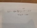
I figured I would draw a small diagram to try and explain. Using a Schottky diode to try and limit the lower voltages trying to get though, putting a capacitor after it will make a small square wave signal between the 2 legs. From what i found out, using a smaller or larger cap will result in a shorter or longer duration of the wave. I'm hoping that by putting the optocoupler in the middle of the parts, with opto in to the diode and opto out to the cap, i can convert the wave 5v without killing it.
The only small values that i have for caps right now is 22pf, 100pf, and 5000pf. I'll get more with the opto order.
(The diode layout is from a coil to square wave diagram online that didn't work.)
20260528_103636.jpg
 
Not sure if you mean schottky with 0.2V voltage drop or a zener? Selection of the input resistor values should limit the current through the opto, maybe you are trying to limit that voltage but it’ll need to be more than 0.2V. A large pull-up resistance on the opto collector should help the collector voltage drop and stay low when the spark triggers the opto. A small (maybe 100nF) capacitor from the collector/processor input pin should extend the duration of the pin going low.
 

Thread Starter

Stuntman225

Joined Apr 28, 2026
76
Not sure if you mean schottky with 0.2V voltage drop or a zener? Selection of the input resistor values should limit the current through the opto, maybe you are trying to limit that voltage but it’ll need to be more than 0.2V. A large pull-up resistance on the opto collector should help the collector voltage drop and stay low when the spark triggers the opto. A small (maybe 100nF) capacitor from the collector/processor input pin should extend the duration of the pin going low.
It's a schottky diode, I do need to limit the voltage getting though. I have 10 new optos and more capacitor sizes to play with on the way, I'll be able to make something work when it gets here.
 
If it's in series with the resistors connected to the -ve pin of the coil it will just drop the voltage in that line by 0.2V. If there is no path to ground, i.e.the opto goes open circuit the high voltage spark will be seen at the circuit board so maybe a resistor to ground would limit this - maybe 2K2 so it doesn't go above 50V which is the traditional safe DC voltage. If you put it between the input to the opto and ground then it will reduce the voltage into the opto to 0.2V which won't fire the internal LED. Perhaps you could sketch a clearer schematic - just the resistors from the coil to the opto and the processor input pin with the necessary related components?
 

Thread Starter

Stuntman225

Joined Apr 28, 2026
76
If it's in series with the resistors connected to the -ve pin of the coil it will just drop the voltage in that line by 0.2V. If there is no path to ground, i.e.the opto goes open circuit the high voltage spark will be seen at the circuit board so maybe a resistor to ground would limit this - maybe 2K2 so it doesn't go above 50V which is the traditional safe DC voltage. If you put it between the input to the opto and ground then it will reduce the voltage into the opto to 0.2V which won't fire the internal LED. Perhaps you could sketch a clearer schematic - just the resistors from the coil to the opto and the processor input pin with the necessary related components?
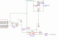
Here's my current wiring plan for when the optos get here. I might use different component values, but the overall schematic should say the same.
Plan B.png
 
I think the schmitt trigger is a good idea to clean up the signal and move between high and low although I still think any noise could be dealt with in code. But if it works it's good! Still not sure about the need for the IN5818? And the opto LED path to ground is via a 5nF capacitor? Is the "COIL" input connected directly to the -ve terminal of the coil?
 

Thread Starter

Stuntman225

Joined Apr 28, 2026
76
I think the schmitt trigger is a good idea to clean up the signal and move between high and low although I still think any noise could be dealt with in code. But if it works it's good! Still not sure about the need for the IN5818? And the opto LED path to ground is via a 5nF capacitor? Is the "COIL" input connected directly to the -ve terminal of the coil?
Noise can be dealt with in code, but I found that higher rpms are ignored and and the code runs slower. I'd like try and fix the issue with hardware as I understand it better.
Yes, the coil signal is coming from the negative coil terminal. I'm not sure the diodes are needed, but I'll try and remove them once I get a working circuit.
I figure with the capacitor on the opto output, there might be trapped voltage between a diode and the cap, and the opto's led will slowly dim as voltage drops. I'm currently waiting for more optos to arrive, so I can't test yet.
Thanks. I'm looking forward to learning that it's working. I'm impressed by your perseverence! Given the high voltage spike, will you be using a string of 1/2 watt resistors (which I think can withstand 250V before breaking down) for the 5K and 22K totals? I think they would go open circuit if they blow - but I'm not sure.
 

Thread Starter

Stuntman225

Joined Apr 28, 2026
76
Thanks. I'm looking forward to learning that it's working. I'm impressed by your perseverence! Given the high voltage spike, will you be using a string of 1/2 watt resistors (which I think can withstand 250V before breaking down) for the 5K and 22K totals? I think they would go open circuit if they blow - but I'm not sure.
I'll be using some 200v 1/2w resistors for whole circuit.
 
The replacement optos showed up, I now have 10 to blow up during testing. I'll try and get around to testing circuit designs on Sunday.
I wonder if another 22K resistor between the circuit and the coil would be a safe way to test to start with? The voltage spike can be as much as 500V. Also, an LED in series with the opto LED would be a visible indication of the input in case the processor is not driving the meter?
 

Thread Starter

Stuntman225

Joined Apr 28, 2026
76
I did some more testing, and here are my results.
1: Putting a capacitor inline with the optocoupler, either before or after, the opto didn't trigger.
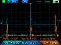
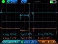
2: Putting a 50 ohm resistor inline with the Schmitt trigger's input makes it trigger mostly accurately (More on that later).
img_06.jpgOrange is coil-, blue is Schmitt output.
3: Putting a small resistor across the opto's input pins help tune the led's turn on point.
4: Putting a resistor from coil- to ground made it so the truck didn't start.
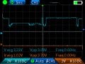
5: The opto triggers unreliably, with the output sometimes staying high or low when it shouldn't.
img_11 (1).jpgBlue is opto output.
6: Trying different low pass filter capacitors didn't change anything. (All of the small caps that i have are ceramic, no idea if that changes anything.)

When the opto is triggering with every spark event properly, the schmitt trigger outputs a clean square wave predictably. From my research, the PC817 might be to slow to work for my application, but it i feel that it should work. My brother has some faster optos that i can borrow, but i haven't gotten a chance to use them yet.

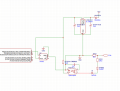
This is the current circuit that I'm using.
Screenshot 2026-06-07 142856.png
 
Good to learn you are getting close! I did question the capacitor in line with the opto in post #112. The cathode of the opto LED does need to be connected to ground as you now have it. My original schematic had a 5nF capacitor in parallel with the opto LED, not in series. Subsequently, I suggested a higher value of opto collector pull up resistor and a small capacitor between the opto collector to ground. This would slow down the rise in collector voltage when the opto transistor turns off. Just the internal pull up resistor (set in code) might be fine or a 47K value with the internal pull up turned off are maybe worth trying.
 

Thread Starter

Stuntman225

Joined Apr 28, 2026
76
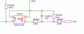
I have made a small break though. If I make a circuit like this,
Screenshot 2026-06-08 081549.png
I get a much cleaner signal going to the opto input.
img_15.jpgI believe the input power to the opto is too little with the current resistors that i have, but i need to figure out a low or high pass filter to remove the little spike at the end of the signal. I found an article where someone made a tachometer filter circuit for a 22re (what i have), but they didn't say what size caps they used.
https://www.dgp.toronto.edu/~mccrae/projects/492project/tachsignal.html
Also, a faster opto didn't seem to make any noticeable difference in the circuit's output.
 
Thread starter Similar threads Forum Replies Date
Ya’akov Feedback and Suggestions 2
Similar threads
Editing is broken suddenly?
Top