 Facebook
 Google
 GitHub
 Linkedin
Thanks all for the replies and input. I will be back out at this car in the coming weeks and will see how I progress.
I have a few things to try, the preferred option would be the one discussed on this thread.
I will update this thread!
I have a few things to try, the preferred option would be the one discussed on this thread.
I will update this thread!
Attachments
-
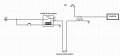 120.8 KB Views: 17
 -
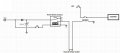 127.3 KB Views: 18
 -
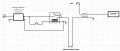 128.4 KB Views: 18
Last edited:


